All-suture suture anchor systems and methods

a suture and anchoring technology, applied in the field of soft tissue to bone repair procedures, can solve the problems of unable to repair, prone to pull out, and likely to be pulled toward the surface of the bone,

Active Publication Date: 2017-04-18
CAYENNE MEDICAL INC
View PDF17 Cites 3 Cited by
  • Summary
  • Abstract
  • Description
  • Claims
  • Application Information

AI Technical Summary

Benefits of technology

[0012]The present invention comprises an all-suture anchor together with an inserter and drill guide to deploy the anchor in bone. The inserter is designed to pull a specific and consistent range of tension each time in order to deploy the anchor in a bone tunnel. The drill guide provides a large footprint at the surface of the bone around the drill hole to protect the bone during anchor deployment.
[0016]The inventive inserter utilizes a knob to turn a screw to apply tension to the floating sutures. This design provides a mechanical advantage and allows the inserter to pull more tension to deploy the anchor than a surgeon can reliably pull by hand to achieve the desired range of deployment tension (60-150 N).
[0017]Another important component of the present inventive system is the drill guide. Most suture anchors on the market utilize a drill guide to help locate and maintain the position of the drill on the bone surface as well as to guide the anchor into the hole at the same angle as the drilled hole. For the described all-suture anchor of the present invention, the drill guide plays an integral role and is designed to aid in the anchor deployment. Since the inserter pulls on the anchor with a significant amount of tension, the opposing reaction force pulls the inserter against the bone surface. If the anchor were deployed without a drill guide, in soft bone, the deployment forces would pull the anchor upwardly toward the surface of the bone and simultaneously pull the inserter shaft downwardly into the bone, and full tension would not be reached. Most drill guides are made from thin-walled tubing to keep the outer diameter as small as possible. However, this thin, knife-kike edge at the tip can create a cylindrical cut into the bone around the tunnel if forced into the bone. This can also happen if the practitioner mallets too hard on the inserter handle. If the inserter handle bottoms out on the drill guide, subsequent malleting will drive the inserter and drill guide into bone and damage the surface. The drill guide used with the described anchor and inserter has a much thicker wall section at the tip that provides a larger surface area to resist the downward forces (applied by the inserter during anchor deployment or by the practitioner during malleting). This downward pressure from the drill guide tip also protects the bone from damage or breaking as the anchor is pulled upwardly during deployment. If the anchor is manually deployed and the practitioner pulls very hard to deploy the anchor, it will expand and the force is then transmitted to the bone above it. If the bone is weak, it could break and leave a large crater on the surface of the bone. In the inventive system, the drill guide helps to prevent this mode of failure.

Problems solved by technology

However, if the anchor is exposed to loads higher than the deployment force, it is likely to be pulled toward the surface of the bone.
This movement can cause slack in the suture and allow a gap to form between the tissue and the bone, resulting in a failed repair.
If it is pulled with too much force during deployment (more than its maximum pull-out force in that bone), it may pull out, especially if the bone is very soft or very hard.
Applying too much tension can cause the anchor to pull out of the bone, especially in very soft or very hard bone.
In very soft bone, excessive tension can cause the deployed anchor to pull upwardly through the soft bone.

Method used


Image

  • All-suture suture anchor systems and methods
  • All-suture suture anchor systems and methods
  • All-suture suture anchor systems and methods

Examples


first embodiment

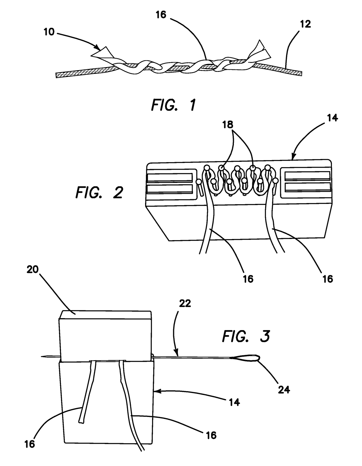
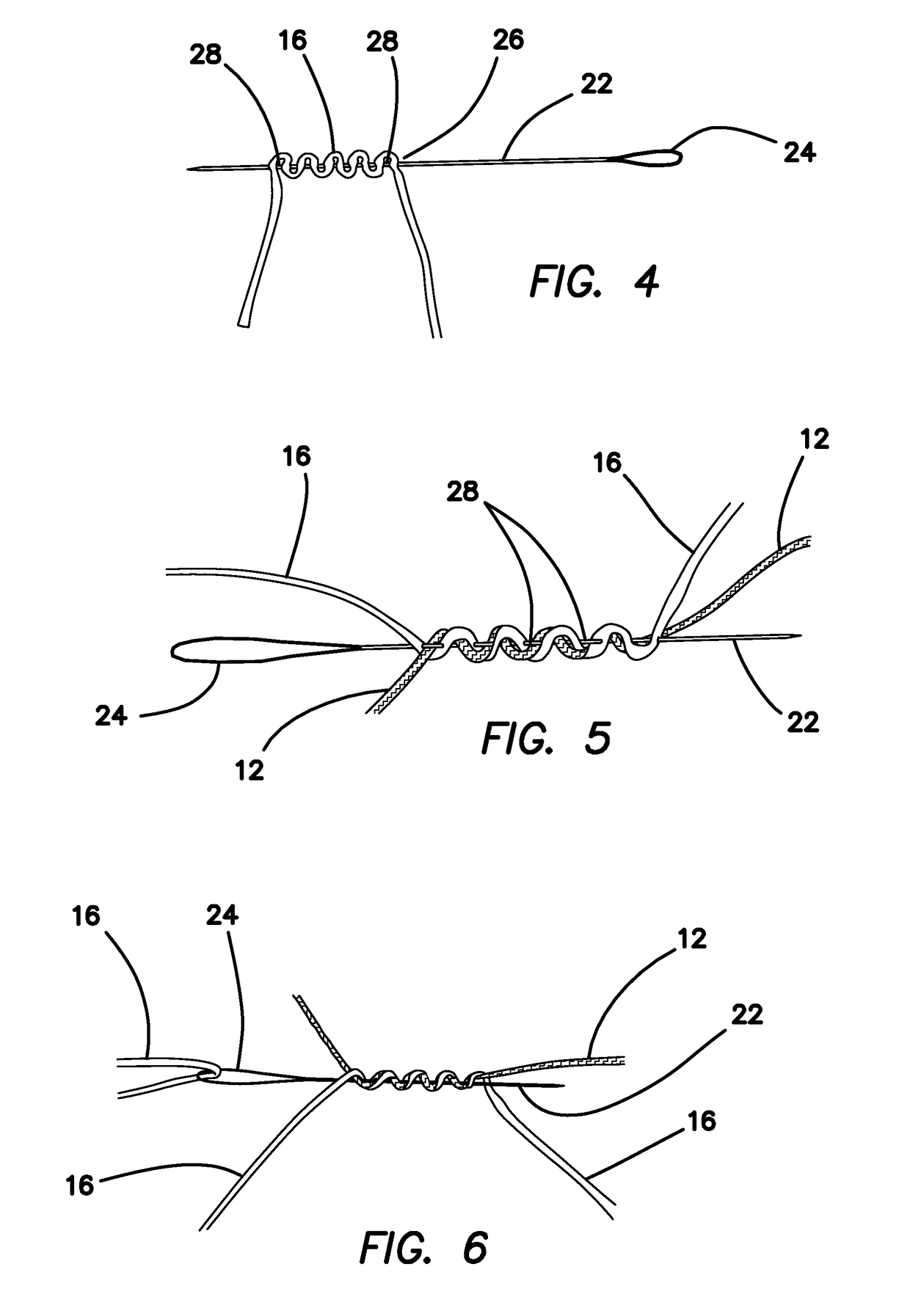
[0039]Thus, FIG. 1 illustrates a suture anchor 10 constructed in accordance with the principles of the present invention. This embodiment is a single-loaded anchor. FIG. 2 illustrates an assembly fixture 14, wherein a piece of size 2 suture 16 (anchor suture) is wrapped around pins 18 of the fixture 14, as shown. As shown in FIG. 3, a cap 20 is placed on the fixture 14 and a needle 22 with a snare loop 24 on one end is pierced through the anchor suture 16. Then, the assembly 26 is removed from the fixture, as shown in FIG. 4.

[0040]Referring to FIG. 5, one free end of the floating suture 12 is passed back and forth through loops 28 formed between the suture 16 and the needle 22 in the previous step. As shown in FIGS. 6 and 7, one end of the anchor suture 16 is placed in the snare loop 24 and pulled back through the suture strand.

[0041]FIG. 8 illustrates a step wherein the floating suture 12 has been pulled tight, and the ends of the anchor suture have been cut off to complete the anc...

second embodiment

[0042]Now with reference to FIG. 9, a suture anchor 10 constructed in accordance with the present invention is illustrated. This embodiment is a double-loaded anchor. This embodiment 10 is constructed as shown in FIGS. 10-18. FIG. 10 illustrates a first step in the method of constructing the double-loaded anchor 10 of FIG. 9, wherein a needle 22 with a snare loop 24 on the end is passed through the core of a size 2 piece of suture 16 (anchor suture). The step is repeated with a second needle 30 having a snare loop 32 being passed through a second piece of suture 16, as shown. In FIG. 11, the long end of second anchor suture 16 is placed into the snare loop 24. The needle 22 is pulled to pull the suture end through the core of the second anchor suture 16. FIG. 12 illustrates the result of this step. Then, the long end of the first anchor suture 16 is placed in the snare loop 32 and pulled through the core of the second anchor suture 16. FIG. 13 illustrates the resulting anchor loop 3...

embodiment 10

[0058]Another alternative suture anchor embodiment 10 is illustrated in FIGS. 24-27. This anchor is constructed by wrapping anchor suture around a pin and tying two alternative half-hitches 62 (FIG. 25). The two limbs are then wrapped around another pin, and more half-hitches 62 are tied. The center loop 64 is wrapped around a larger pin to allow for easier loading onto the inserter inner shaft 38. The floating suture or sutures are then passed through the loops 66 (created by the pins) to complete the construct.

[0059]This anchor is constructed by forming a double loop of suture, then wrapping one of the free ends around the loop approximately twenty times. The loop is then tightened around two posts a distance apart by pulling both free ends. This creates a loop, similar to the anchor loop of the previous double-loaded anchor embodiment 10 of FIGS. 10-18. The remaining construction steps are the same as previously described—the anchor is wrapped around a snare with alternating twis...


PUM


Abstract

A method of anchoring soft tissue to a suitable bone site, using a soft suture anchor, includes steps of disposing the soft suture anchor on a shaft of an inserter, and securing a proximal end of a tensioning suture limb, extending proximally from the soft suture anchor, to structure in a handle of the inserter, so that it is maintained in place at a first level of holding tension (Thold). The inserter shaft is inserted into a bone hole at a desired procedural site, so that the soft suture anchor is positioned at a location where it is to be anchored. A further step involves actuating a control mechanism in the inserter handle to move the structure proximally to apply a second level of deployment tension (Tload) to the tensioning suture limb.

Description

[0001]This application claims the benefit under 35 U.S.C. 119(e) of the filing date of Provisional U.S. Application Ser. No. 61 / 948,543, entitled All-Suture Anchor with Inserter, filed on Mar. 5, 2014, and of the filing date of Provisional U.S. Application Ser. No. 62 / 094,866, entitled All-Suture Anchor with Inserter, filed on Dec. 19, 2014. Both of these prior applications are herein expressly incorporated herein by reference, in their entirety.BACKGROUND OF THE INVENTION[0002]There are many soft-tissue to bone repair procedures, such as rotator cuff, SLAP and Bankart lesion repairs, or reconstruction of labral tissue to the glenoid rim, in which a surgeon needs to secure tissue in close contact with bone by implanting an anchor, pre-loaded with suture, into a hole drilled in the bone at the desired anchor location. Commonly, the anchor which the sutures are attached to is made of either plastic such as PEEK or metal such as Titanium or Stainless Steel. Such anchors function like a...

Claims


Application Information

Patent Timeline
Patent Type & Authority Patents(United States)
IPC IPC(8): A61B17/04A61B17/00A61B90/00
CPCA61B17/0401A61B17/0487A61B17/0467A61B17/0483A61B90/03A61B2017/00526A61B2017/0406A61B2017/0409A61B2017/049A61B2017/0411A61B2017/0474A61B2017/0488A61B2017/0496A61B2017/0477A61B17/0482A61B17/1796A61F2002/0882
Inventor NASON, KEVIN S.NGUYEN, HOANGBAIRD, KEVIN N.HARPER, DEREK J.
Owner CAYENNE MEDICAL INC
Why Eureka
Try Eureka