Flap drive system

a drive system and flap technology, applied in the direction of door/window accessories, furniture parts, wing accessories, etc., can solve the problems of high cost and inability to mount to different mechanical actuating units, and achieve the effects of accurate positional relationship, compact structure, and weight differen

Active Publication Date: 2017-04-18
JULIUS BLUM GMBH
View PDF47 Cites 4 Cited by
  • Summary
  • Abstract
  • Description
  • Claims
  • Application Information

AI Technical Summary

Benefits of technology

[0010]In a further embodiment, it has proven advantageous if the transmission of the transmission stage can alter, that is to say increase or reduce, the torque from the electric drive to the mechanical actuating unit as in that way it is also possible to advantageously move flaps of differing weight.
[0011]In that respect, it has been found to be particularly advantageous if the transmission stage has a mounting for the electric drive as in that way the electric drive can be mounted to the transmission stage quickly and in accurate positional relationship.
[0012]Equally, it has been found to be advantageous if the transmission stage can be fixed to the mechanical actuating unit and / or the furniture carcass as mounting of the transmission stage can thus be effected in different ways. It is equally advantageous if the drive unit can be mounted to the transmission stage after the transmission stage is mounted to the mechanical actuating unit as in that way the transmission stage does not have to be separated from the mechanical actuating unit.
[0013]It has proven to be particularly advantageous in that respect if the transmission stage can be fixed to the furniture carcass or the mechanical actuating unit even when the mechanical actuating unit is already mounted to the furniture carcass as it is then not necessary to dismantle the mechanical actuating unit from the furniture carcass to fit the transmission stage.
[0014]It has proven advantageous in that respect if the mechanical actuating unit, the transmission stage and the electric drive can respectively be connected together in such a way that their side surfaces lie against each other. It is possible in that way to achieve an extremely compact structure which takes up the minimum amount of space in the furniture carcass.
[0015]It has proven particularly advantageous in that respect if the mechanical actuating unit, the transmission stage and the electric drive are adapted to be releasably assembled together. That makes a positive contribution to the maintenance-friendliness of the flap drive system as in that way the entire flap drive system does not have to be replaced if one of the units should be defective.

Problems solved by technology

The disadvantage there is that this flap drive system is only designed for mechanical actuating units which are sized for this system and therefore cannot be mounted to different mechanical actuating units.
It is thus necessary to produce, for each mechanical actuating unit, an electric drive which has specific dimensions for same, and that is linked to high cost levels.

Method used


Image

  • Flap drive system
  • Flap drive system
  • Flap drive system

Examples


Embodiment Construction

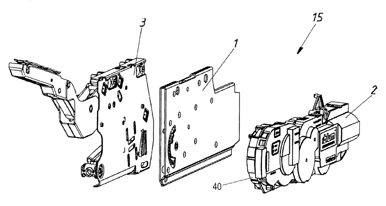
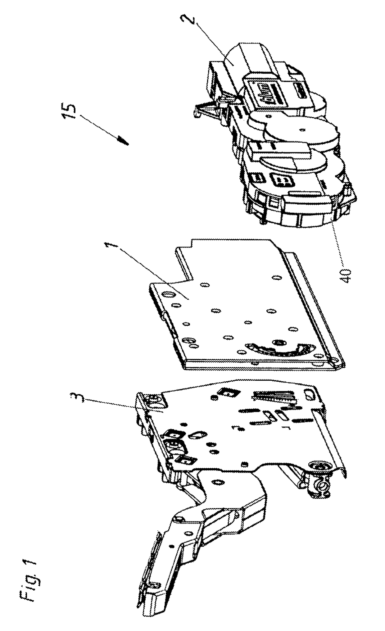
[0023]FIG. 1 shows a flap drive system 15 comprising a mechanical actuating unit 3, a transmission stage 1 and an electric drive 2. It will be seen from FIG. 1 that the transmission stage 1 represents a self-contained component separate from the mechanical actuating unit 3 and the electric drive 2.

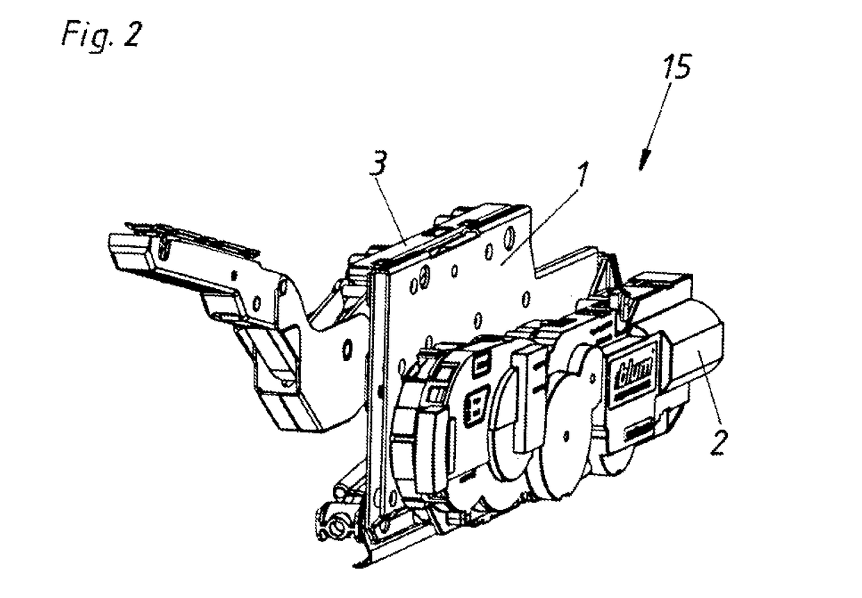
[0024]FIG. 2 shows a flap drive system 15 on which the three assemblies—namely the transmission stage 1, the electric drive 2 and the mechanical actuating unit 3—are connected together.

[0025]FIG. 3 shows an exploded view of the transmission stage 1 comprising a right-hand (second) housing portion 5 and a left-hand (first) housing portion 6 between which there is a transmission 4. A pin (not shown here) of the electric drive is introduced into the pin receiving section 8 through an opening 12 in the right-hand housing portion 5. The projection 11 in turn acts through the opening 13 of the left-hand housing portion 6 on a corresponding receiving means (not shown) in the mechanical actuating ...


PUM


Abstract

The invention relates to a flap drive system for a flap which is movably mounted on a furniture carcass. The flap drive system is arranged on a sidewall of the furniture carcass. The flap drive system includes a mechanical actuating unit having an actuating arm that can be connected to the flap and an accumulator acting upon the actuating arm, and an electric drive, fastened on the mechanical actuating unit for driving the flap. The electric drive has at least one electric motor, and a gear stage which allows the transmission of force from the electric drive onto the mechanical actuating unit. The gear stage is designed as a separate component, and has a housing that is independent from the mechanical actuating unit and the electric drive or an independent mounting plate.

Description

[0001]This application is a Continuation of International application No. PCT / AT2010 / 000162, filed May 12, 2010, the entire disclosure of which is incorporated herein by reference.BACKGROUND OF THE INVENTION[0002]The invention concerns a flap drive system for a flap mounted movably to a furniture carcass, the flap drive system being arranged at a side wall of the furniture carcass. The flap drive system includes a mechanical actuating unit having an actuating arm which can be connected to the flap and a force storage means acting on the actuating arm, and an electric drive fixed to the mechanical actuating unit for driving the flap. The electric drive has at least one electric motor and a transmission stage which permits a transmission of force from the electric drive to the mechanical actuating unit.[0003]Flap drive systems for a flap mounted movably to a furniture carcass are already known and are illustrated, for example, in WO 2008 / 134786. The disadvantage there is that this fla...

Claims


Application Information

Patent Timeline
Patent Type & Authority Patents(United States)
IPC IPC(8): A47B95/00E05F15/63E05F1/10
CPCE05F15/63E05F1/1058E05Y2201/71E05Y2600/522E05Y2800/205E05Y2800/22E05Y2800/264E05Y2800/72E05Y2900/20
Inventor FRIESENECKER, GERALDBOHLE, WOLFGANG
Owner JULIUS BLUM GMBH
Why Eureka
Try Eureka