Laser microscope which expands the dynamic range of an intensity signal and suppresses degradation of a light detecting portion

a laser microscope and intensity signal technology, applied in the field of laser microscopes, can solve the problems of difficult setting conditions, low overall brightness, and buried noise in the brightness of extremely weak light from areas other than photoresponsive sites, and achieve the effect of expanding the dynamic range of an intensity signal and restricting the degradation of a light detecting portion

Active Publication Date: 2017-04-18
EVIDENT CORP
View PDF9 Cites 2 Cited by
  • Summary
  • Abstract
  • Description
  • Claims
  • Application Information

AI Technical Summary

Benefits of technology

[0007]The present invention provides a laser microscope that expands the dynamic range of the intensity signal and that suppresses degradation of a light detecting portion.
[0026]The present invention affords advantages in that the dynamic range of an intensity signal is expanded and degradation of a light detecting portion is restricted.

Problems solved by technology

On the other hand, setting the full scale on the basis of the brightness of light from a photoresponsive site on the specimen that is given a light stimulus may cause the brightness of extremely weak light from areas other than the photoresponsive site to become buried in noise.
In addition, even if the specimen exhibits a strong response, setting a low laser power or low HV of the PMT so that the brightness does not saturate causes the overall brightness to become low, and makes it difficult to set conditions, including the position of the photoresponsive site and so forth.

Method used


Image

  • Laser microscope which expands the dynamic range of an intensity signal and suppresses degradation of a light detecting portion
  • Laser microscope which expands the dynamic range of an intensity signal and suppresses degradation of a light detecting portion
  • Laser microscope which expands the dynamic range of an intensity signal and suppresses degradation of a light detecting portion

Examples


first embodiment

[0047]A scanning laser microscope (laser microscope) according to a first embodiment of the present invention will be described below with reference to the drawings.

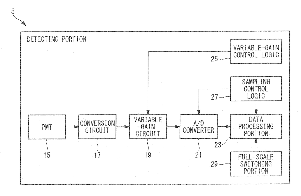
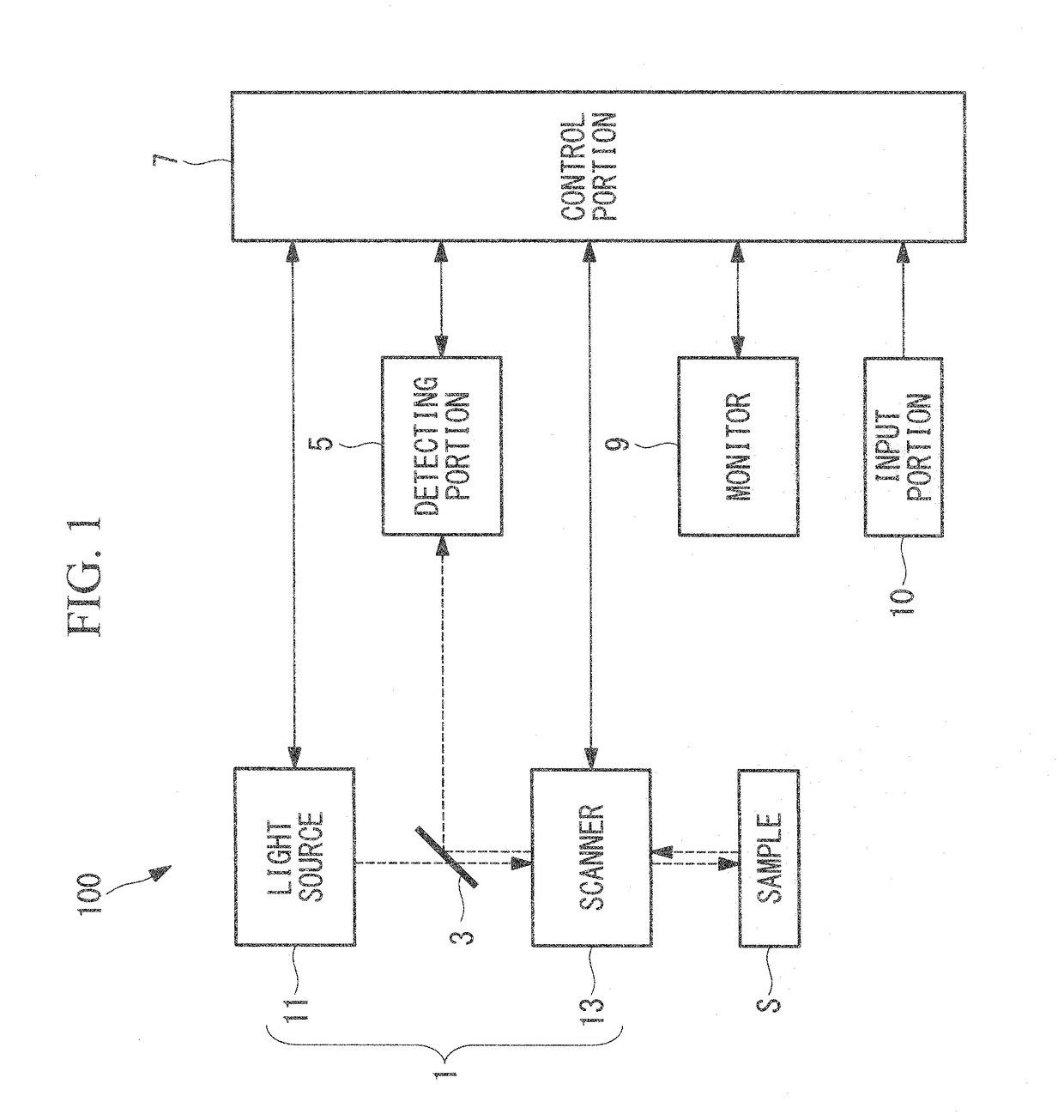
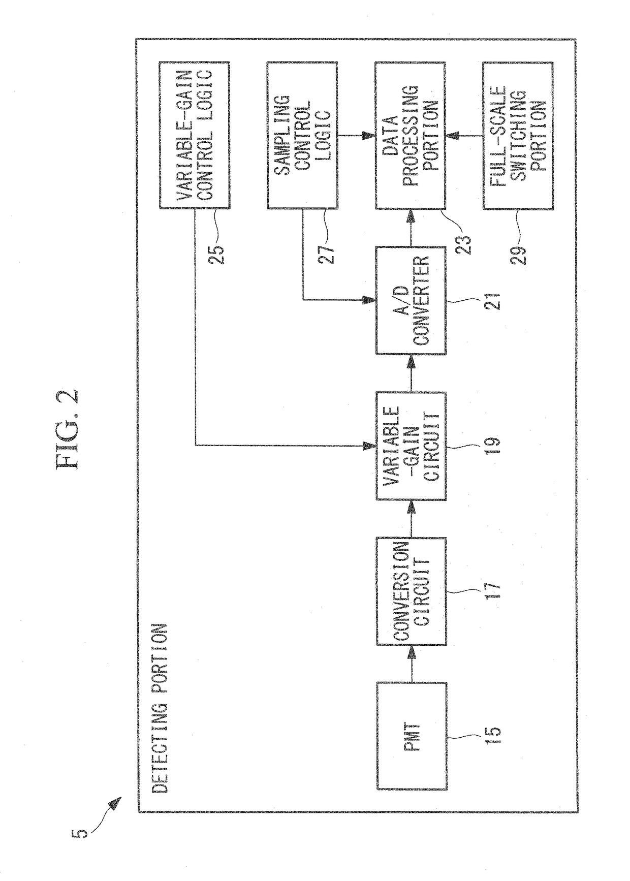
[0048]As shown in FIG. 1, a scanning laser microscope 100 according to this embodiment includes, for example, a light irradiating portion 1 that irradiates a sample (specimen) S with laser light; a dichroic mirror 3 that splits off, from the light path of the laser light, fluorescence (light) generated in the sample S irradiated with the laser light by the light irradiating portion 1; a detecting portion 5 that detects the fluorescence split off by the dichroic mirror 3; a control portion (switching determination portion) 7 that performs control of the light irradiating portion 1 and the detecting portion 5, image creation, determination of whether to switch the observation mode, or the like; a monitor 9 that displays an image created by the control portion 7 and so forth; and an input portion 10 that allows the user to ...

second embodiment

[0091]Next, a scanning laser microscope (laser microscope) according to a second embodiment of the present invention will be described.

[0092]The scanning laser microscope 100 according to this embodiment differs from the first embodiment in that, as shown in FIG. 12, a data processing portion (information converting portion) 31 that separates the digital data into two channels and outputs the separated data is provided instead of the data processing portion 23.

[0093]The configuration other than the data processing portion 31 is the same as that in the first embodiment, and therefore a description thereof will be omitted in what follows. In addition, parts having the same configuration as those in the scanning laser microscope 100 according to the first embodiment are assigned the same reference signs, and a description thereof is omitted.

[0094]The data processing portion 31 includes a computational processing portion 33 that converts the digital data sent from the A / D converter 21 i...


PUM


Abstract

A laser scanning microscope includes a light irradiating portion that irradiates a sample; a PMT that detects fluorescence from the sample and outputs an intensity signal; a data processing portion that converts the intensity signal to brightness information at each pixel; a full-scale setting portion that can set a normal full scale that is smaller than the intensity signal when a light stimulus is given and an expanded full scale that is larger than the normal full scale, as a maximum range of the intensity signal that can be converted to brightness information; and a control portion that determines whether to switch between a normal observation mode and a stimulation observation mode; wherein the full-scale switching portion sets the normal full scale in the normal observation mode and sets the expanded full scale in the stimulation observation mode.

Description

CROSS-REFERENCE TO RELATED APPLICATIONS[0001]This application is based on Japanese Patent Application No. 2014-212732, the contents of which are incorporated herein by reference.TECHNICAL FIELD[0002]The present invention relates to a laser microscope.BACKGROUND ART[0003]In the related art, there is a known laser microscope provided with a photomultiplier tube (PMT) serving as a detector that detects light and outputs an intensity signal of the detected light (for example, see Patent Literature 1). A PMT has a risk of suffering degradation when an excessive level of light is incident thereon, and therefore, in a conventional laser microscope, the maximum range of the intensity signal from the PMT which can be converted to brightness information (hereinafter referred to as “full scale”) is set to a range that does not cause degradation of the PMT, and the laser light power, a high-voltage (HV) applied to the PMT, or the like is adjusted so that the output signal from the PMT does not ...

Claims


Application Information

Patent Timeline
Patent Type & Authority Patents(United States)
IPC IPC(8): G02B21/06G02B21/16G02B21/36G02B21/00
CPCG02B21/365G02B21/002G02B21/008G02B21/0076G02B21/06G02B21/16
Inventor HASHIMOTO, KATSUYUKISASAKI, KUNIHIKOMATSUKAWA, YASUNARIARAYA, AKINORI
Owner EVIDENT CORP
Why Eureka
Try Eureka