
Structure of power input end and power output end of power supply device

Active Publication Date: 2017-04-25
CHYNG HONG ELECTRONICS
View PDF4 Cites 1 Cited by
  • Summary
  • Abstract
  • Description
  • Claims
  • Application Information

AI Technical Summary

Benefits of technology

The present invention provides an improved structure for a power supply device that reduces the heat dissipation area, improving efficiency. This is achieved through a perpendicular power output end and heat dissipation holes in the back plate and protection cover. Additionally, the protection cover is easily disassembled for convenient assembly and disassembly of the power wire.

Problems solved by technology

The power consumption is also increasing, which results in a large amount of waste heat.
In general, the waste heat generated by the computer is accumulated in the power supply, which causes the temperature of the power supply is gradually increased.
If the heat does not be exhausted, it may affect the efficiency of the internal components of the power supply and shorten the service life of the power supply.
This design blocks the guide of heat dissipation.

Method used


Image

  • Structure of power input end and power output end of power supply device
  • Structure of power input end and power output end of power supply device
  • Structure of power input end and power output end of power supply device

Examples


Embodiment Construction

[0016]Embodiments of the present invention will now be described, by way of example only, with reference to the accompanying drawings.

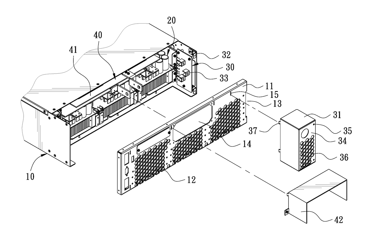
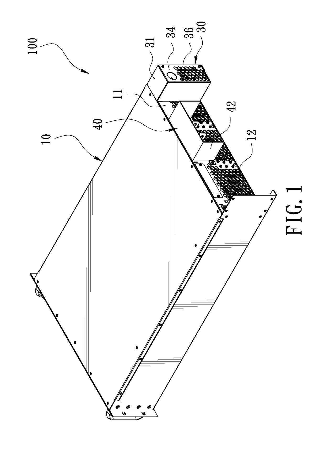
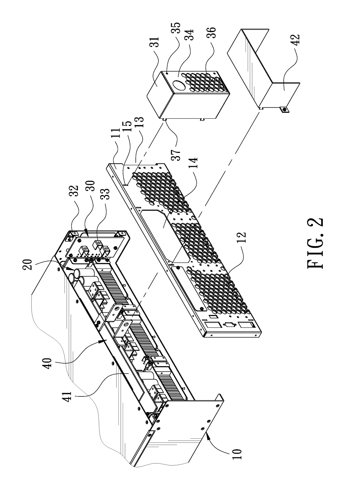
[0017]FIG. 1 is a perspective view of the present invention. FIG. 2 is an exploded view of the present invention. The present invention discloses an improved structure of a power input end and a power output end of a power supply device 100. In the embodiment of the present invention, the power supply 100 comprises a casing 10, a main body 20, a power input unit30, and two power output units 40.

[0018]A rear side of the casing 10 is longitudinally provided with a back plate 11. The back plate 11 has a plurality of first heat dissipation holes 12. The first heat dissipation holes 12 are arranged in the form of a honeycomb. The back plate 11 has an input hole 13 and an output hole 14 close to the first heat dissipation holes 12. The back plate 11 is further provided with an engaging groove 15.

[0019]The main body 20 is disposed in the casing 10. The main ...


PUM


Abstract

An improved structure of a power input end and a power output end of a power supply device is provided. The power supply includes a casing and a main body. A rear side of the casing is provided with a back plate having first heat dissipation holes. One side of an inner wall of the casing is provided with a power input end and a protection cover. A rear side of the protection cover is provided with an upright plate having a threaded hole and second heat dissipation holes parallel to the first heat dissipation holes. The interior of the casing is provided with two power output ends each in the form of a plate perpendicular to the back plate. The present invention lowers the sheltered area of the back plate to form a better heat dissipation structure. The protection cover can be disassembled easily.

Description

BACKGROUND OF THE INVENTION[0001]1. Field of the Invention[0002]The present invention relates to a structure of a power input end and a power output end of a power supply device, and more particularly to an improved structure of a power input end and a power output end of a power supply device.[0003]2. Description of the Prior Art[0004]With the development of technology, the efficacy of computers is improved increasingly. The power consumption is also increasing, which results in a large amount of waste heat. Because the structures of various computer equipment and instruments are gradually sophisticated, it is strict for the quality of a power supply accordingly. In general, the waste heat generated by the computer is accumulated in the power supply, which causes the temperature of the power supply is gradually increased. If the heat does not be exhausted, it may affect the efficiency of the internal components of the power supply and shorten the service life of the power supply.[0...

Claims


Application Information

Patent Timeline
IPC IPC(8): G06F1/20H05K7/20G06F1/18
CPCG06F1/20H05K7/20554G06F1/189H05K7/20563G06F1/188
Inventor LIN, MU-CHUN
Owner CHYNG HONG ELECTRONICS
Learn More