Air purification unit

a technology of air purification unit and air purification chamber, which is applied in the direction of separation process, dispersed particle separation, chemistry apparatus and processes, etc., can solve the problems of low significant risk to human health, and increase the cost of the system, so as to improve the air pollutant removal efficiency, improve the surface area, and enhance the effect of photocatalytic oxidation

Active Publication Date: 2017-05-02
NANO & ADVANCED MATERIALS INST
View PDF11 Cites 1 Cited by
  • Summary
  • Abstract
  • Description
  • Claims
  • Application Information

AI Technical Summary

Benefits of technology

[0013]Unlike the traditional air purification system, the air purification unit of the presently claimed invention provides several advantages. The fin structure is able to increase the surface area for depositing photocatalyst, the contact area between air pollutants in the airflow and the photocatalyst, as well as the irradiation area irradiated by the UV light from the UV lamp, thereby enhancing the photocatalytic oxidation and improving air pollutant removal efficiency.
[0014]Meanwhile, the fin structure provides empty spaces for air to pass through, thus preventing the fin structure from inducing large air resistance. The fin density of the fin structure is preferably 1-2 fins / cm, which optimizes the performance of the air purification unit with the balance of trade offs between the air flow rate and the air pollutant removal efficiency.

Problems solved by technology

In building circulating systems, pollutants from various sources contribute to indoor air pollution, which poses a significant risk towards human health.
However, the implementation of the excimer lamps increases substantially the cost of the system.
However, the amount of the photocatalyst coated on the metal substrate is limited, resulting in low air pollutant removal efficiency.
Nevertheless, the felt induces high air resistance, leading to high loading of the air flow generation unit.
Nevertheless, the performance of air pollutant removal is not effective since only limited amount of photocatalyst is coated on the metal substrate.

Method used


Image

  • Air purification unit
  • Air purification unit
  • Air purification unit

Examples


Embodiment Construction

[0032]In the following description, air purification units, and the fin structures of said air purification units are set forth as preferred examples. It will be apparent to those skilled in the art that modifications, including additions and / or substitutions, may be made without departing from the scope and spirit of the invention. Specific details may be omitted so as not to obscure the invention; however, the disclosure is written to enable one skilled in the art to practice the teachings herein without undue experimentation.

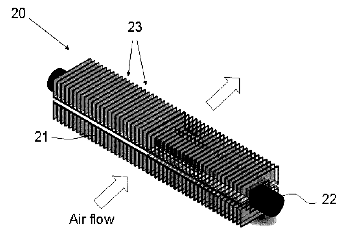
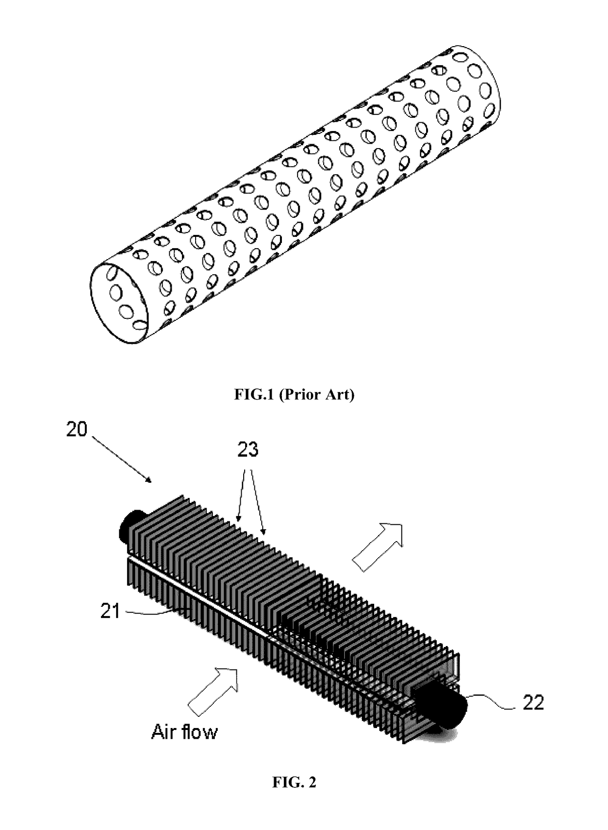
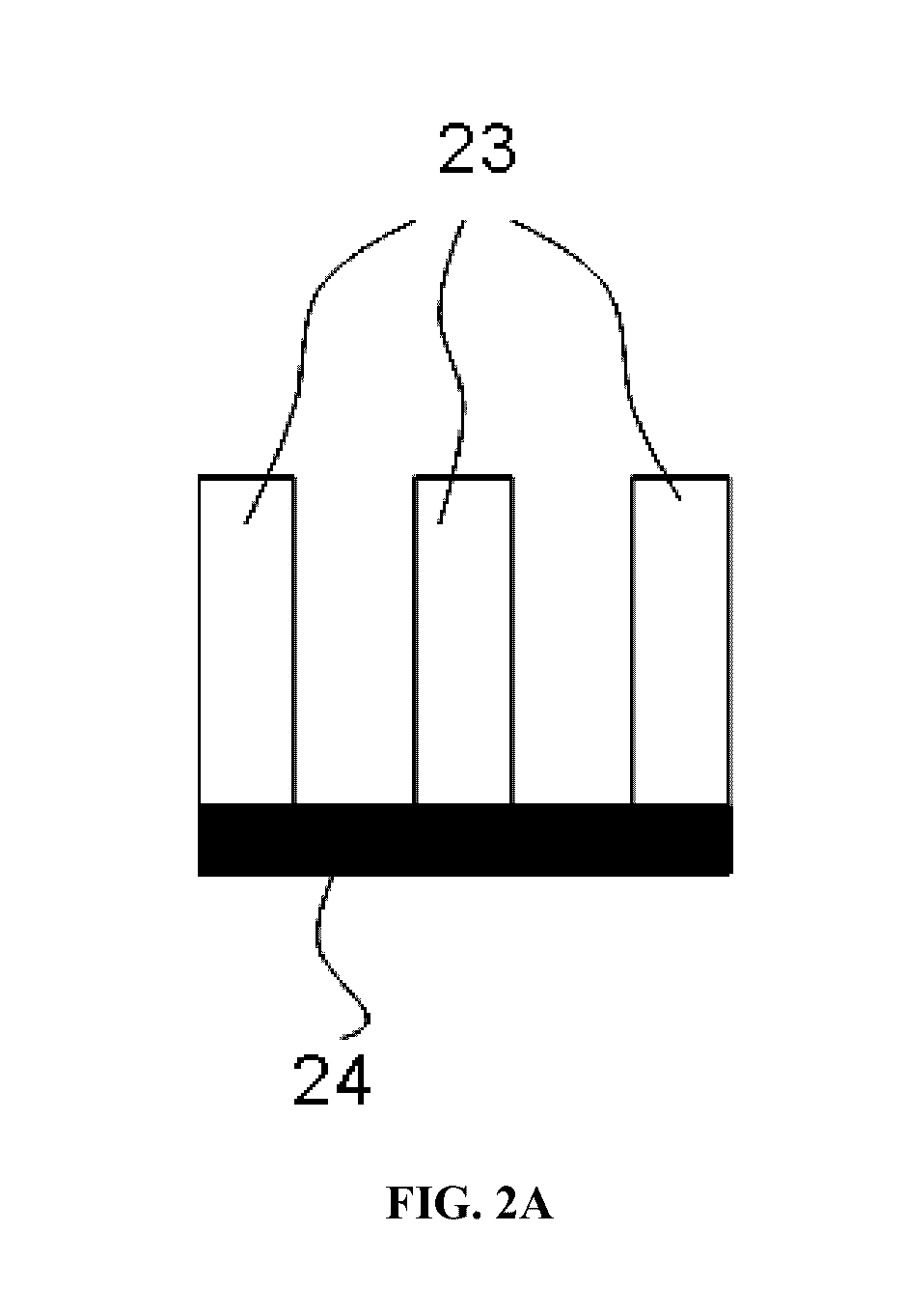
[0033]FIG. 2 is a perspective view of an air purification unit with a fin structure having a rectangular shape according to an embodiment of the presently claimed invention. The air purification unit 20 comprises a fin structure 21 and an UV lamp 22. The UV lamp 22 is located along the axis of the fin structure 21, and enclosed by the fin structure 21. The fin structure 21 is rectangular in shape, and comprises a plurality of fins 23 and a fin holder 24 (as s...


PUM

PropertyMeasurementUnit
wavelengthsaaaaaaaaaa
thicknessaaaaaaaaaa
UV light reflectanceaaaaaaaaaa

Abstract

The presently claimed invention provides a photocatalytic air purification unit, comprising a fin structure and an UV lamp. The fin structure comprises a plurality of fins coated with a layer of photocatalyst, and said fin structure is able to increase the surface area for photocatalyst coating, ultimately increasing air pollutant removal efficiency with minimum air resistance. The air purification unit of the present invention is preferably installed in a HVAC system.

Description

CROSS REFERENCE TO RELATED APPLICATION[0001]Pursuant to 35 U.S.C. §119(e), this is a non-provisional patent application which claims benefit from U.S. provisional patent application Ser. No. 61 / 853,040 filed Mar. 27, 2013, and the disclosure of which is incorporated herein by reference.COPYRIGHT NOTICE[0002]A portion of the disclosure of this patent document contains material, which is subject to copyright protection. The copyright owner has no objection to the facsimile reproduction by anyone of the patent document or the patent disclosure, as it appears in the Patent and Trademark Office patent file or records, but otherwise reserves all copyright rights whatsoever.FIELD OF THE INVENTION[0003]The present invention relates to an air purification unit, and particularly relates to an air purification unit with photocatalyst.BACKGROUND[0004]It is well known in the art that when titanium dioxide is exposed to light, a photocatalytic reaction takes place, and such reaction is able to de...

Claims


Application Information

Patent Timeline
Patent Type & Authority Patents(United States)
IPC IPC(8): A61L9/20B01D53/86B01D53/88
CPCA61L9/205B01D53/8687B01D53/885B01D2255/20707B01D2255/802B01D2257/708B01D2258/06B01D2259/804
Inventor KEUNG, LOK HANG
Owner NANO & ADVANCED MATERIALS INST
Why Eureka
Try Eureka