Real-time compositional analysis of hydrocarbon based fluid samples

a composition analysis and hydrocarbon based fluid technology, applied in the field of formation fluid analysis, can solve the problems of large processing time, difficult response and quantification, and inability to quantitatively measure the individual hydrocarbon moieties of c in the current downhole analysis technique,

Active Publication Date: 2017-05-02
SCHLUMBERGER TECH CORP
View PDF26 Cites 6 Cited by
  • Summary
  • Abstract
  • Description
  • Claims
  • Application Information

AI Technical Summary

Problems solved by technology

Current downhole analysis techniques, however, do not provide quantitative measurement of the individual hydrocarbon moieties for C2, C3, C4, C5 and molecules with more than six carbon atoms are indistinguishable.
Unfortunately, processing the data in this manner requires substantial processing time.
However, this method requires that conditions of the analysis during the calibration procedure and during the experiments are identical, which is a challenge for the variety of downhole conditions worldwide.
This method requires bringing the “standard” downhole, mixing it with the sample of the formation mixture, identification of the “standard” response and its quantification, which is often very challenging.
However, in case of analysis of such a complex mixture as a crude oil, not all components will elute from the column (e.g., resins, asphaltenes, and very heavy saturates).
Furthermore, integration and summation of all eluted peaks introduces significant error in the analysis results.
In some embodiments including comparing the determined optical property with the determined independent composition evaluation, an unfavorable comparison is indicative of a lack of quality in at least one of the determination of the optical property and the determination of the independent composition evaluation.

Method used


Image

  • Real-time compositional analysis of hydrocarbon based fluid samples
  • Real-time compositional analysis of hydrocarbon based fluid samples
  • Real-time compositional analysis of hydrocarbon based fluid samples

Examples


Embodiment Construction

[0041]In the following detailed description of the preferred embodiments, reference is made to accompanying drawings, which form a part thereof, and within which are shown by way of illustration, specific embodiments, by which the invention may be practiced. It is to be understood that other embodiments may be utilized and structural changes may be made without departing from the scope of the invention.

[0042]The particulars shown herein are by way of example and for purposes of illustrative discussion of the embodiments of the present invention only and are presented in the case of providing what is believed to be the most useful and readily understood description of the principles and conceptual aspects of the present invention. In this regard, no attempt is made to show structural details of the present invention in more detail than is necessary for the fundamental understanding of the present invention, the description taken with the drawings making apparent to those skilled in t...


PUM

PropertyMeasurementUnit
mole percentageaaaaaaaaaa
weight fractionaaaaaaaaaa
wavelengthsaaaaaaaaaa

Abstract

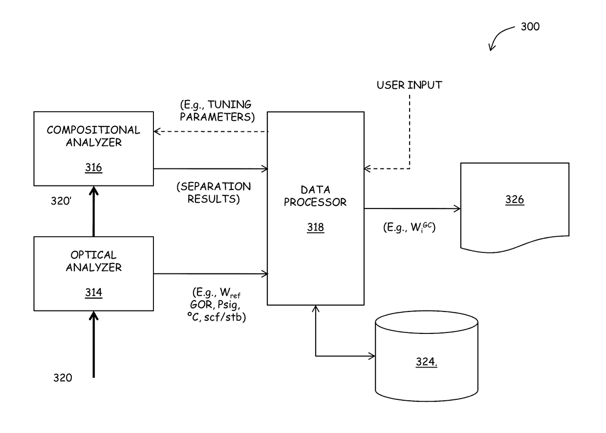
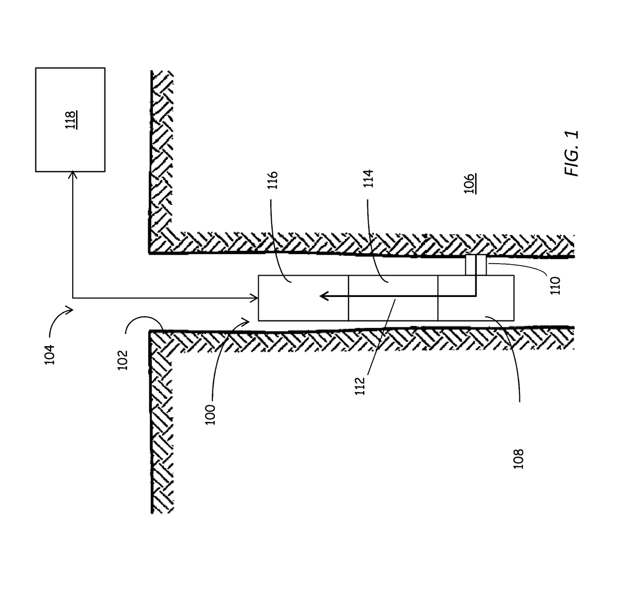
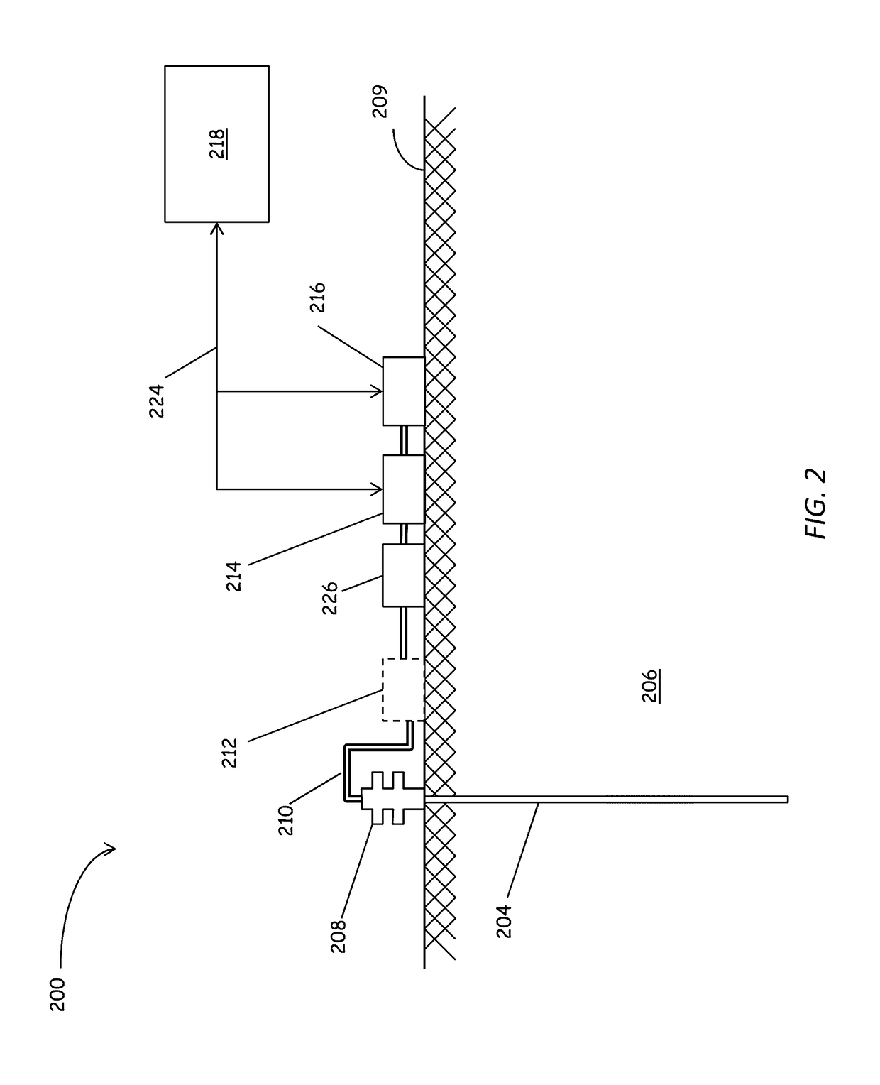
Accurate, real-time formation fluids analysis can be accomplished using the systems and techniques described herein. A fluid analyzer includes a first mode of analysis, such as an optical analyzer, configured to determine a physical (optical) property of a fluid sample. The fluid analyzer also includes another mode of analysis, such as a composition analyzer, such as a gas chromatograph, configured to determine a component composition of the fluid sample. A data processor is configured to determine a quantity, such as a weight percentage, of a target component of the fluid sample in response results obtained from the first and second modes of analysis. Beneficially, the results are obtained at least in near real-time, allowing for interim results, such as results from the first analyzer to be used for one or more of tuning the compositional analyzer and for implementing quality control.

Description

BACKGROUND[0001]1. Technical Field[0002]This application relates generally to formation fluid analysis as may be accomplished downhole or at a surface. More particularly, this application relates to detection and identification of classes of interest within a formation fluid using a chromatography-based device.[0003]2. Background Information[0004]Downhole fluid analysis (DFA) is a rapidly growing discipline in wireline logging and has become a keystone in reservoir evaluation. DFA addresses the failed and overly optimistic assumption that oil reservoirs contain of “one giant tank of homogeneous hydrocarbon.” Beneficially, DFA can be used to find compositional gradients as well as to identify compartments. Such analyses are typically based on bulk optical spectroscopy of samples of formation fluid to determine concentrations or ratios of components in sample fluid.[0005]More recently, sophisticated optical measurement techniques have been developed to, among other things, determine m...

Claims


Application Information

Patent Timeline
Patent Type & Authority Patents(United States)
IPC IPC(8): E21B49/08G01N21/3504G01N30/86G01N21/359G01N21/64G01N21/3577E21B49/10G01N33/28G01N30/88
CPCG01N33/2823E21B49/10G01N21/3504G01N21/359G01N21/3577G01N21/643G01N30/8658G01N2030/8854
Inventor ZHDANEEV, OLEGHARRISON, CHRISTOPHERZUO, YOUXIANGZHANG, DINGANSTEINECKER, WILLIAM H.LAMBERTUS, GORDON R.BOSTROM, NEIL
Owner SCHLUMBERGER TECH CORP
Why Eureka
Try Eureka