Cable gland assembly

a technology of cable glands and assemblies, which is applied in the direction of cable terminations, cable inlet sealing means, electric cable installations, etc., can solve the problems of lack of appropriate weather-tight sealing elements, difficulty in physically connecting cable wires to connector pins or sockets, and difficulty in converting one connector for another, so as to increase the tensile or pull strength of shielded cables

Active Publication Date: 2017-05-02
REVISION MILITARY SOLDIER POWER LLC
View PDF7 Cites 28 Cited by
  • Summary
  • Abstract
  • Description
  • Claims
  • Application Information

AI Technical Summary

Benefits of technology

[0013]The shielded cable includes a plurality of conductive strands each surrounded by an electrically insulating layer. An inner strength member comprising bundled fibers is disposed parallel to the plurality of conductive stands. The plurality of conductive strands and the inner strength member are surrounded by an outer strength member comprising bundled fibers. The strength members increase the tensile or pull strength of the shielded cable. The plurality of conductive strands, the inner strength member and the outer strength member are surrounded by a cable shielding layer. The cable shielding layer is a cylindrical tube formed of braided metal material that tends to prevent EMI from being transmitted through the cable shielding layer. The cable shielding layer is surrounded by an electrically insulating cable sheath.

Problems solved by technology

Connectors are thus often required to be as small as possible which makes it difficult for assemblers to physically connect the cable wires to the connector pins or sockets.
Furthermore, connectors or cable glands on device enclosures, panels, bulkheads, or the like are typically permanently attached, making it difficult to exchange one connector for another as may be required if, for example, an existing connector is damaged or if there is otherwise a need to install a different connector.
However one problem with both of these conventional connectors is a lack of appropriate weather-tight sealing elements to moisture seal the cable gland and the enclosure housing that the cable gland interfaces with in a manner that improves performance in harsh environmental conditions or provides protection against damage even for submersion in liquids.

Method used


Image

  • Cable gland assembly
  • Cable gland assembly
  • Cable gland assembly

Examples


Embodiment Construction

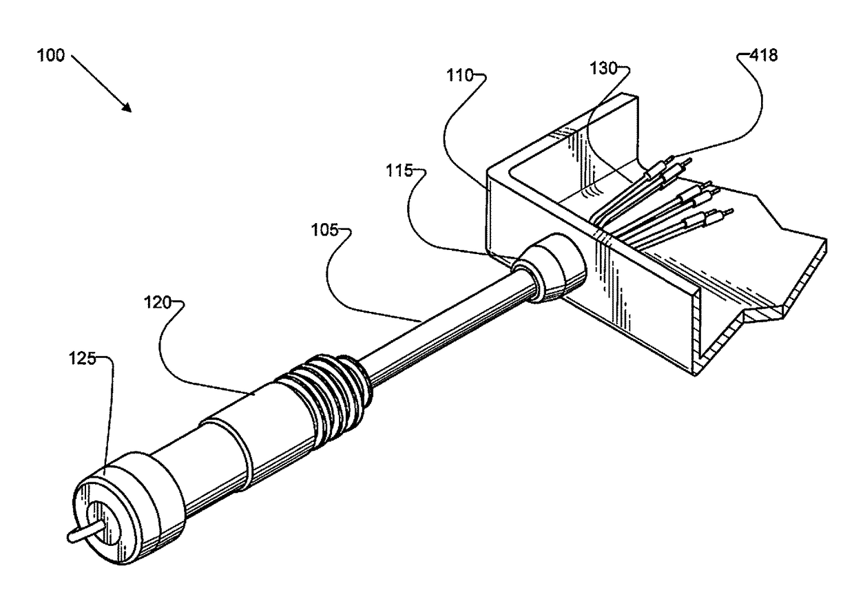
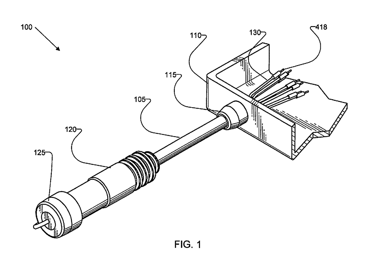
[0029]Referring to FIG. 1, a cable assembly (100) for attaching a shielded cable (105) to a device enclosure (110) through a cable gland assembly (115) is depicted in isometric and cutaway views. The shielded cable assembly includes the shielded cable (105) terminated at an external end thereof by an external electrical connector (120). In one non-limiting exemplary embodiment, the external electrical connector (120) is a multi-pin connector usable to provide an electrical interface between an electrical device, such as a rechargeable DC battery or a battery operated power device, not shown.

[0030]The external electrical connector (120) is preferably configured for use in harsh outdoor environments and optionally includes a moisture sealing end cap (125) usable to prevent cable pins and or sockets of the external electrical connector (120) from exposure to moisture and other environmental contaminants as well as preventing an electrical shock hazard. In particular the external electr...


PUM


Abstract

A cable gland assembly for attaching a shielded cable to an electronic enclosure includes a cable gland housing enclosing and in electrical contact with exposed cable shielding of the shielded cable and providing an electrically conductive pathway between the cable shielding and the electronic enclosure. The cable gland housing further encloses a shield pressure ring disposed to hold the exposed cable shielding in contact with the cable gland housing, a weather gasket, and an exposed portion of a cable strength member. The cable gland assembly includes environmental molding disposed within the cable gland housing to bond to and fix in place the exposed cable shielding, shield pressure ring, weather gasket, and exposed cable strength member. An outer molding is disposed around the cable gland housing.

Description

1 COPYRIGHT NOTICE[0001]A portion of the disclosure of this patent document may contain material that is subject to copyright protection. The copyright owner has no objection to the facsimile reproduction by anyone of the patent document or the patent disclosure, as it appears in the Patent and Trademark Office patent files or records, but otherwise reserves all copyright rights whatsoever. The following notice shall apply to this document: Copyright© Protonex Technology 2016.2 BACKGROUND OF THE INVENTION[0002]2.1 Field of the Invention[0003]The exemplary, illustrative technology herein relates to cable gland assemblies, methods of use, and methods of manufacturing cable gland assemblies. In particular, the exemplary, illustrative technology relates to improved cable gland assemblies and methods of manufacturing of cable gland assemblies for attaching shielded cables to device enclosures, bulkheads, panels, and the like.[0004]2.2 The Related Art[0005]Entering an electronic device en...

Claims


Application Information

Patent Timeline
Patent Type & Authority Patents(United States)
IPC IPC(8): H02G15/06H02G15/013H02G15/007
CPCH02G15/06H02G15/013H02G15/007H02G3/0666H02G15/068
Inventor LONG, DAVID N.KIMBALL, PAUL W.PLOURDE, JOHN R.NGUYEN, DAT VANPERSKY, JOSHUA E.PIELA, NICHOLAS J.
Owner REVISION MILITARY SOLDIER POWER LLC
Why Eureka
Try Eureka