Method for operating a wind power plant

a technology for wind power plants and wind power installations, applied in the direction of instruments, machines/engines, mechanical equipment, etc., can solve the problems of wind power installation damage, high cost, prone to error, etc., and achieve the effect of easy calibration and/or adjustment, high degree of accuracy

Active Publication Date: 2017-05-09
WOBBEN PROPERTIES GMBH
View PDF16 Cites 2 Cited by
  • Summary
  • Abstract
  • Description
  • Claims
  • Application Information

AI Technical Summary

Benefits of technology

[0010]Embodiments of the invention may simplify calibration and adjustment of at least one loading sensor and / or to increase as much as possible the reliability of such a calibration and / or adjustment. At least one embodiment of the invention seeks to propose an alternative solution.
[0019]Preferably adjustment is performed when bringing the wind power installation into operation and / or after a stoppage of the rotor and / or at the end of an operation for maintaining the wind power installation. If calibration or adjustment is also effected after a stoppage of the rotor, that is to say when the rotor re-starts, that makes it possible in particular to monitor and possibly adapt calibration and adjustment when the installation is brought into operation. Any changes in the load measuring means or other parameters in the course of time can thus be easily taken into consideration.
[0020]Wind power installations usually undergo maintenance procedures at regular intervals, which also usually make it necessary to stop the rotor. At the end of the maintenance operation the rotor is then re-started and thus, as a concluding activity of such a maintenance procedure, calibration and / or adjustment can thus be easily monitored and optionally corrected or renewed.
[0023]Preferably the at least one rotor blade is adjustable and in particular is turned out of the wind for performing the described load measurement procedure so that no or little energy is taken from the wind. In that way on the one hand an idle spinning mode can also be implemented with a medium or strong wind. If the load measuring means are so arranged that they are also adjusted upon adjustment of the rotor blade, the fact of the rotor blade being turned out of the wind also has the result that it is entirely or partially turned in a direction in which the load measuring means measure the weight force on the rotor blades at the location of a pressure loading due to the wind. In other words, with such an adjustment, the weight force acts in optimum fashion in precisely the direction in which the wind force acts on the rotor blade, if the rotor blade is not turned out of the wind. Accordingly, for load measurement for calibration and / or adjustment purposes, the influence of the wind, even if it occurs, can be minimized and the influence of the—known—weight force can be maximized and thus the load measurement can be carried out with a high degree of accuracy, having regard to previously known weight forces which occur at the rotor.
[0024]Preferably at least one strain gauge, in particular two or more strain gauges for each rotor blade, is used as the load measuring means. Thus a tried-and-tested measuring means can be used for detecting blade loadings and easily calibrated and / or adjusted. The use of a plurality of strain gauges makes it possible to take account of different loading directions and / or redundancy measurements can be afforded.

Problems solved by technology

If excessively strong wind is incident on the rotor blades the wind power installation can suffer damage—depending on the frequency or strength.
Such calibration with adjustment can be very complicated and expensive and also liable to error because in that case associated loading values, which are to be recorded elsewhere, are to be associated with the measured sensor values.
That can be triggered by aging phenomena both of the rotor blades and also the sensors and also due to other reasons such as for example defects in the sensor or its fixing.
If such changes are slight and / or occur slowly there is the danger that they remain unnoticed.

Method used


Image

  • Method for operating a wind power plant
  • Method for operating a wind power plant
  • Method for operating a wind power plant

Examples


Embodiment Construction

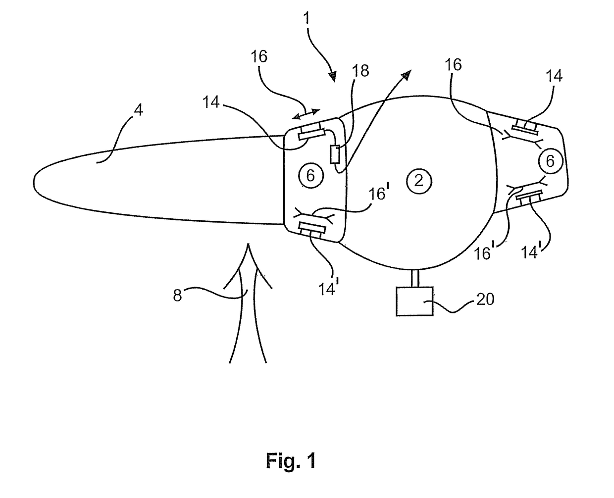
[0035]The plan view in FIG. 1 shows a portion of a rotor 1 having a hub 2 and a rotor blade 4 out of a total of three rotor blades on the rotor 1. The rotor blade 4 is fixed to the hub by means of a blade adaptor 6. The blade adaptor 6 is fixed rotatably to the hub in order to turn the rotor blade 4 into the wind, out of the wind or into an intermediate position. A wind measuring means 20 for generally measuring the prevailing wind is shown in the region of the hub 2.

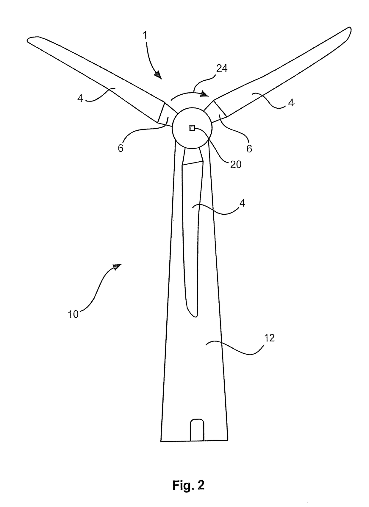
[0036]Reference 8 denotes an arrow specifying the direction of the wind which in usual operation acts on the rotor blade. In this case the wind direction corresponds to the direction of the view of a wind power installation as shown in FIG. 2. FIG. 2 diagrammatically shows an overall view of the wind power installation 10 and in that case illustrates the aerodynamic rotor 1 with three rotor blades 4. The wind power installation pylon 12 is also shown.

[0037]FIG. 1 thus shows a plan view of the wind power installation 10 ...


PUM

PropertyMeasurementUnit
pitch angleaaaaaaaaaa

Abstract

The present invention concerns a method of operating a wind power installation, wherein the wind power installation has an aerodynamic rotor in the form of a horizontal-axis rotor having a hub with at least one rotor blade, and provided on the rotor is at least one load measuring means for detecting a wind loading on the rotor, the method includes the steps: rotating the rotor of the wind power installation without or with a slight wind loading for calibration of the load measuring means and in that case recording a load measurement with the load measuring means, and calibrating the load measuring means based on the load measurement and previously known weight forces occurring at the rotor.

Description

BACKGROUND[0001]Technical Field[0002]The present invention concerns a method of operating a wind power installation and a wind power installation.[0003]Description of the Related Art[0004]A wind power installation having a horizontal-axis rotor has at least one and usually three rotor blades which in ordinary operation rotate about a horizontal axis due to the wind incident thereon to generate electric energy by means of that rotary movement. If excessively strong wind is incident on the rotor blades the wind power installation can suffer damage—depending on the frequency or strength. Such loadings due to excessively strong wind can be countered, for example, by the rotor blades being at least partially turned out of the wind. That is also referred to as pitching.[0005]To be able to initiate such measures or other measures for relieving the load on the wind power installation it is necessary to detect corresponding loadings due to strong wind. A continuously strong and uniform wind ...

Claims


Application Information

Patent Timeline
Patent Type & Authority Patents(United States)
IPC IPC(8): G01L25/00F03D17/00
CPCG01L25/00F03D17/00F05B2270/802Y02E10/72
Inventor EDEN, GEORG
Owner WOBBEN PROPERTIES GMBH
Why Eureka
Try Eureka