Auto-cleaning and auto-zeroing system used with a photo-ionization detector

a technology of photo-ionization detector and auto-zeroing system, which is applied in the direction of lighting and heating apparatus, heating types, applications, etc., can solve the problems of ionization chamber ionization, adsorption of contaminants, dirt particles, oil particles,

Active Publication Date: 2017-05-09
R2CD HLDG PTE
View PDF30 Cites 13 Cited by
  • Summary
  • Abstract
  • Description
  • Claims
  • Application Information

AI Technical Summary

Benefits of technology

[0037]the splitter connector allows ambient air from the cleaning (flushing) cycle left inside the ionization chamber; to be trapped within the ionization chamber,thereby allowing the cleaned and filtered ambient air to be ionized and the air borne contaminants and pollutants deposited in the ionization chamber to be removed.
[0038]Preferably, during the cleaning (flushing) cycle of an auto-cleaning and auto-zeroing system for use with a PID, the splitter connector allows air borne contaminants and pollutants flushed out from the ionization chamber during the cleaning (flushing) cycle to pass through the outflow conduit into the environment.
[0039]Preferably, during the cleaning (ionization) cycle of an auto-cleaning and auto-zeroing system for use with a PID, the splitter connector allows ambient air from the cleaning (flushing) cycle left inside the ionization chamber to be trapped within the ionization chamber, thereby allowing the cleaned and filtered ambient air to be ionized and the air borne contaminants and pollutants deposited in the ionization chamber to be removed.

Problems solved by technology

After prolonged usage of the PID device, contamination such as dirt particles, oil particles, fluxes, water particles especially during high humidity condition, and contaminants adsorbed during prolong exposure to air, often builds up inside the ionization chamber.
These contaminants are attracted to the electrodes, thus settling on them.
In turn, the accuracy of volatile gas concentration measurement is affected as these contaminants interfere with the movement and collection of the ions and electrons on the electrodes.
The contamination which have settled on the window of the PID also reduces the intensity of UV light and consequently affects the accuracy of the volatile gas concentration measurement.

Method used


Image

  • Auto-cleaning and auto-zeroing system used with a photo-ionization detector
  • Auto-cleaning and auto-zeroing system used with a photo-ionization detector
  • Auto-cleaning and auto-zeroing system used with a photo-ionization detector

Examples


Embodiment Construction

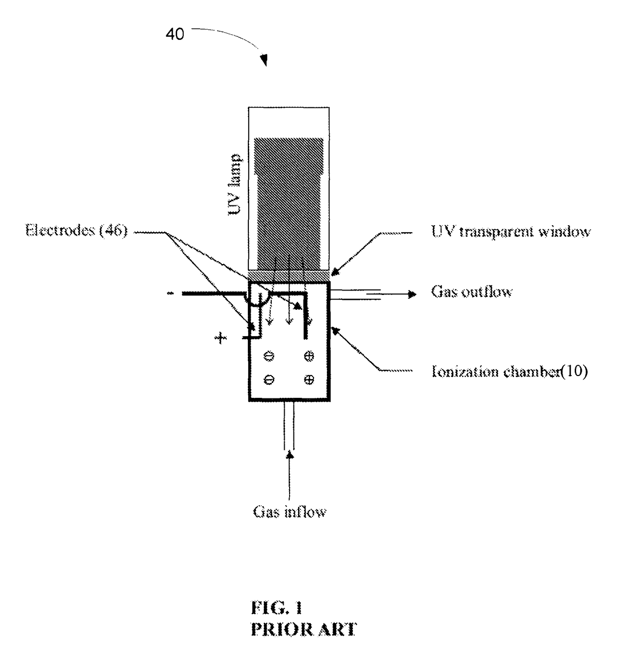
[0084]FIG. 1 is an illustration of a simple PID device (40) known in the art. The PID device (40) has an UV lamp through which UV light is shone through an optically clear window into an ionization chamber (10).

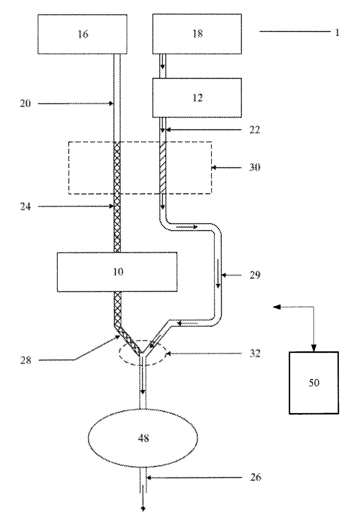
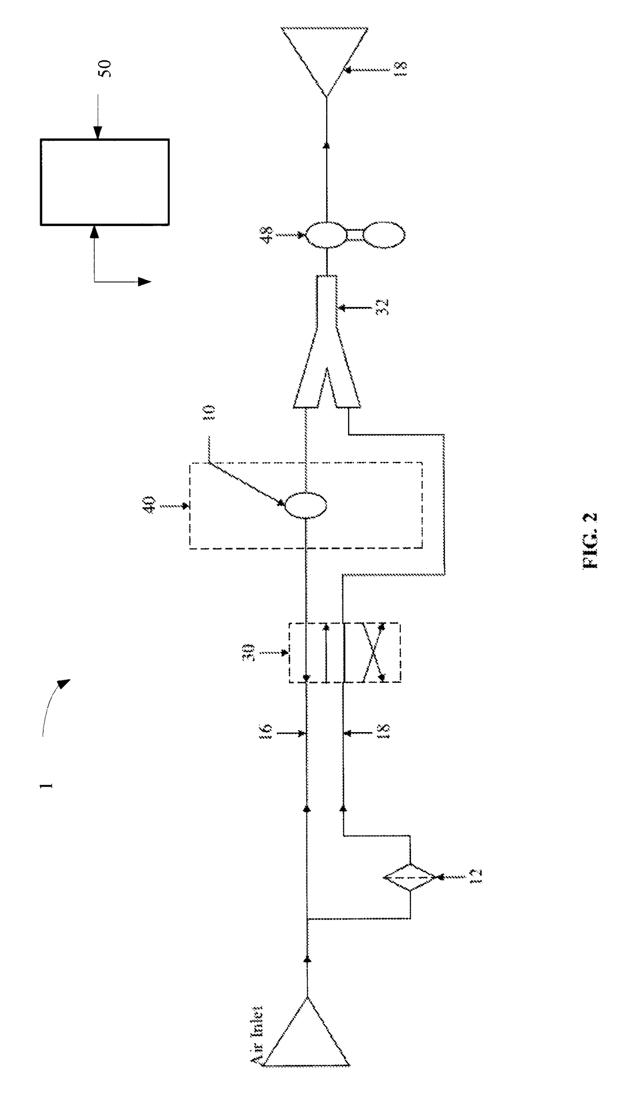
[0085]The novel features of the auto-cleaning and auto-zeroing system (1) of this invention is a 4 / 2 valve (30) and the use of two conduits (20,22) to control and regulate alternatively, the flow of ambient gas (16) and clean filtered air into the ionization chamber (10). The ambient gas (16) flows through a 1st conduit (20) into the ionization chamber (10) without passing through any cleaning chamber (12) to remove pollutants and contaminants in the ambient gas (16). Ambient air (18) flows through a 2nd conduit (22) through a cleaning chamber (12) which removes air borne dust particles, pollutants and gaseous materials. Ambient air (18) is thus cleaned and filtered before being entering the ionization chamber (10).

[0086]FIG. 2 shows the auto-cleaning and auto-zeroing system ...


PUM

PropertyMeasurementUnit
energyaaaaaaaaaa
ionization potentialaaaaaaaaaa
concentrationaaaaaaaaaa

Abstract

An auto-cleaning and auto-zeroing system (1) comprises a first conduit for flow of ambient gas (16) and a 2nd conduit (22) for flow of ambient air (18). A cleaning chamber (12) removes impurities from ambient air (18). The 1st conduit (20) and 2nd conduit (22) are connected to a valve, operated by the continuous motor, which continuously draws ambient gas (16) or cleaned and filtered ambient air (18) through the system. Cleaned and filtered ambient air (18) enters the ionization chamber (10) to carry out a cleaning (flushing) and a cleaning (ionization) cycle. In this manner, contaminants and pollutants left in the ionization chamber (10) from the measurement of ambient gas (16) are flushed out and removed.

Description

FIELD OF THE INVENTION[0001]This invention relates to an auto-cleaning and auto-zeroing system used with a volatile gas detector, particularly a continuously operated Photo-Ionization Detector (PID).DISCUSSION OF PRIOR ART[0002]A PID as known in the art is illustrated in FIG. 1. Such devices are generally used for monitoring gases for:[0003]Industrial hygiene and safety[0004]Indoor air quality[0005]Environmental contamination[0006]Cleanroom air quality[0007]A PID uses high-energy photons, typically in the ultraviolet (UV) range, to break gas molecules into positively charged ions. A typical PID for detection of volatile gases as shown in FIG. 1 consist of an ionization chamber, an UV lamp with sufficient energy to ionize the ionizable molecule, a voltage source for the accelerating electrode, and an amplifier capable of measuring the current flow. The ionizable molecules are bombarded by high-energy photons and are ionized when these molecules absorb high energy UV light. UV light e...

Claims


Application Information

Patent Timeline
Patent Type & Authority Patents(United States)
IPC IPC(8): F24F7/06G01N27/64G01N27/68
CPCG01N27/64G01N27/68
Inventor CHAN, WAI HOE
Owner R2CD HLDG PTE
Why Eureka
Try Eureka