
Sodium-cesium ionization detector

a technology of ionization detector and sodium-cesium, which is applied in the direction of instruments, nuclear elements, greenhouse gas reduction, etc., can solve the problems of cs-137, a fission product, out of liquid sodium coolant and into the vapor treatment system, and the consequences of cesium release are relatively small

Active Publication Date: 2018-03-20
TERRAPOWER
View PDF15 Cites 5 Cited by
  • Summary
  • Abstract
  • Description
  • Claims
  • Application Information

AI Technical Summary

Benefits of technology

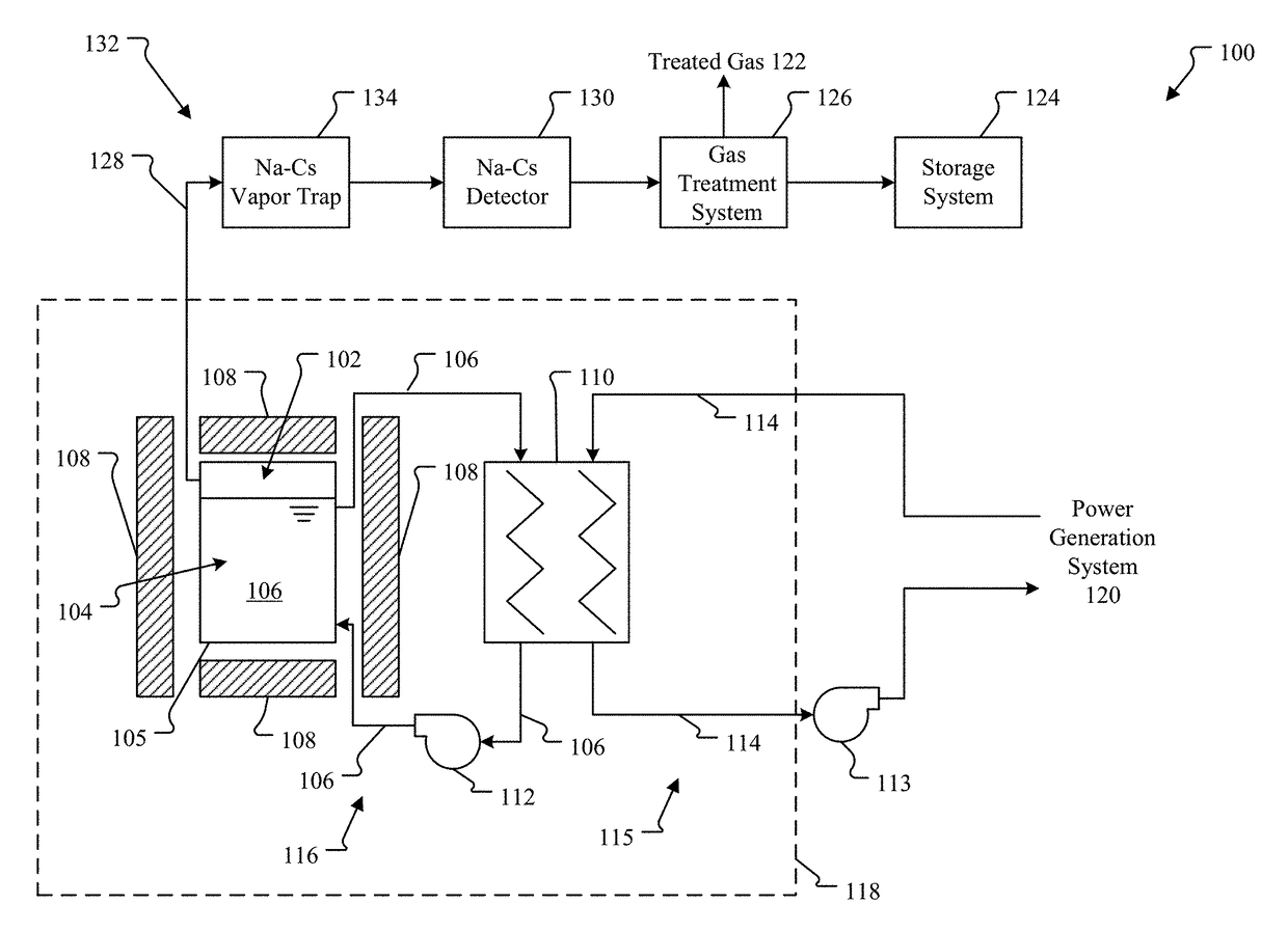
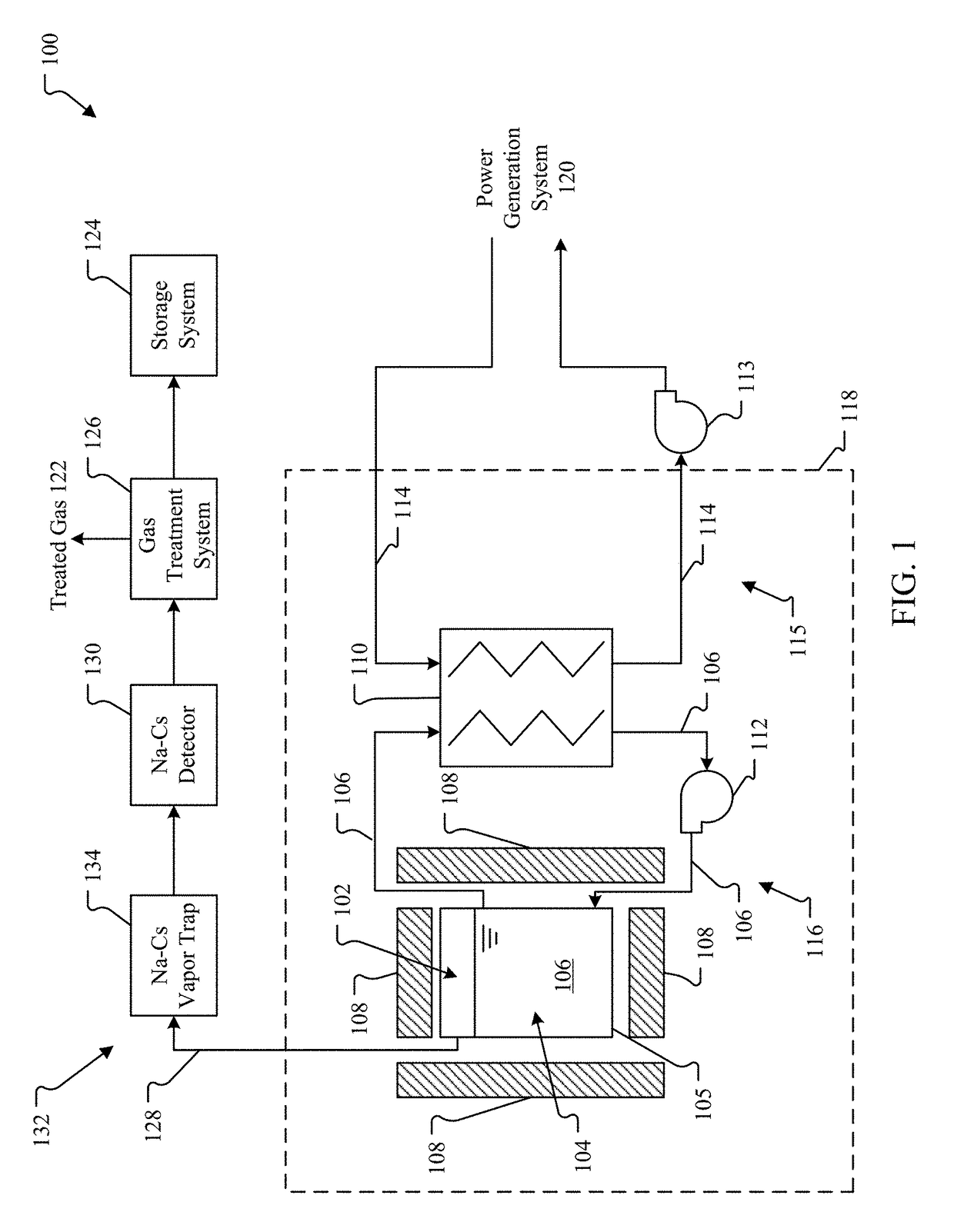
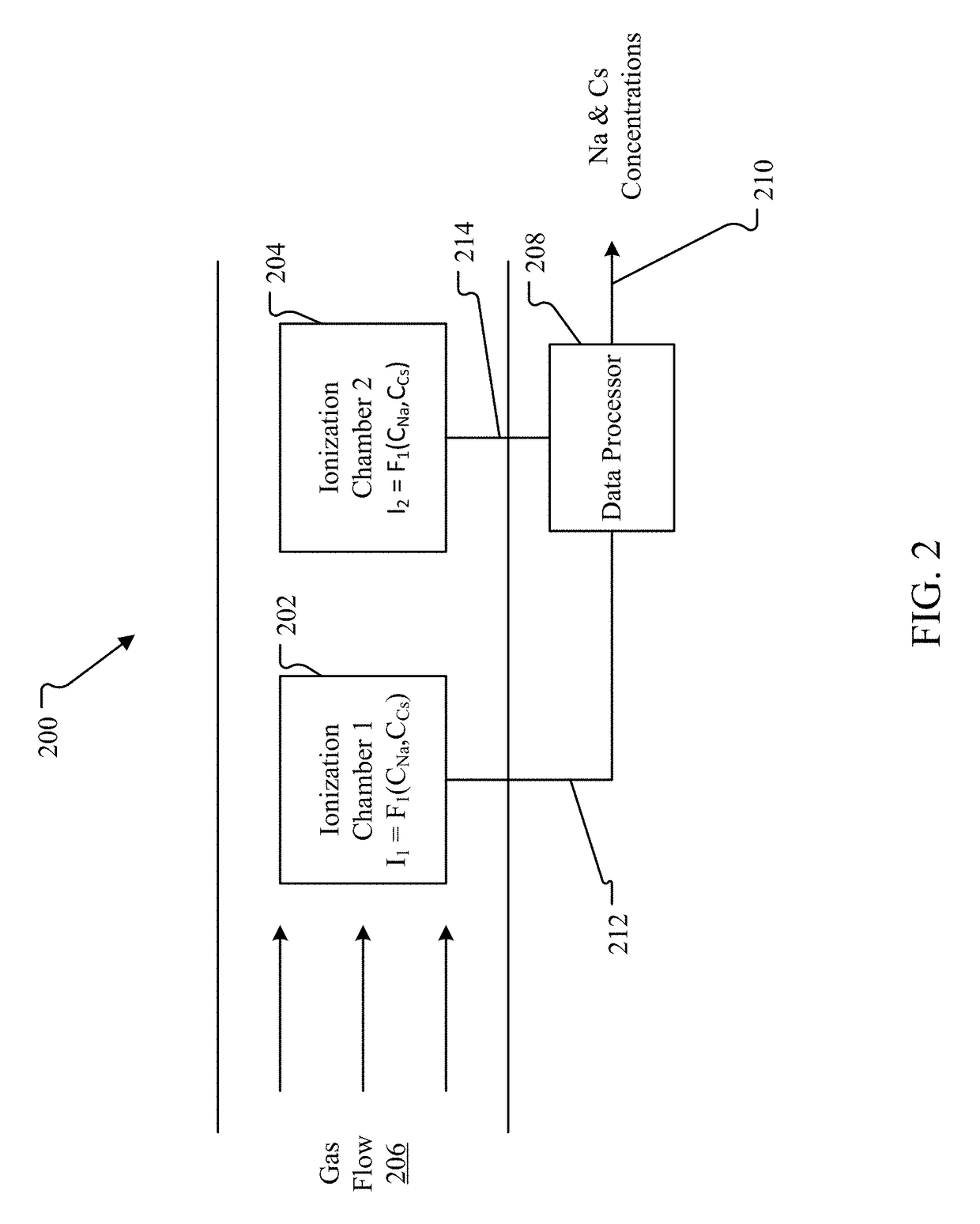
The patent describes a new system for detecting both sodium and cesium in gas using two different ionization chambers. This is important for monitoring the operation of sodium-cooled nuclear reactors, as the release of cesium from the coolant can cause issues in the reactor. The detection system can be used in various contexts where the presence of both sodium and cesium needs to be known simultaneously. The technical effect of this patent is to provide a more effective and accurate way of detecting the presence of both analytes in a gas stream.

Problems solved by technology

One drawback identified during the operation of the research reactors was the carryover of Cs-137, a fission product, out of the liquid sodium coolant and into the vapor treatment system of the reactor.
In most previous reactor designs, the consequences of cesium release were relatively small because the quantity released from a few failed fuel pins was small.

Method used


Image

  • Sodium-cesium ionization detector
  • Sodium-cesium ionization detector
  • Sodium-cesium ionization detector

Examples


embodiment 400

[0042]FIG. 4 illustrates several views of an embodiment 400 of an ionization chamber using a coiled filament. FIG. 4 includes a wireframe view and a shaded view showing the coiled filament anode 402a. The anode 402a is within a tubular cathode 402c provided with a number of circular openings in the side wall, referred to as perforations 402p to allow gas to enter the annular region and come in contact with the heat from the anode 402a. Insulation 402i is illustrated on portions of the anode and cathode wiring. This insulation 402i controls the location of the electrical field created between the anode 402a and cathode 402c as well as the location of the high temperature zone around the anode 402a.

embodiment 500

[0043]FIG. 5 illustrates several views of an embodiment 500 of an ionization chamber that is the same as that of FIG. 4 except that it uses a straight filament. FIG. 5 includes a wireframe view and a shaded view showing the coiled filament anode 502a. The anode 502a is within a tubular cathode 502c provided with a number of circular openings in the side wall, referred to as perforations 502p to allow gas to enter the annular region and come in contact with the heat from the anode 502a. Insulation 502i is illustrated on portions of the anode and cathode wiring. This insulation 502i controls the location of the electrical field created between the anode 502a and cathode 502c as well as the location of the high temperature zone around the anode 502a.

[0044]Instead of a circular coil as shown in FIGS. 3 and 4, or a straight coil as shown in FIG. 5, any other geometries may be used, as long as the geometries, and thus the Cs and Na functions, of the two ionization chambers are different....


PUM

PropertyMeasurementUnit
temperatureaaaaaaaaaa
concentrationaaaaaaaaaa

Abstract

Sodium-cesium detection systems and methods for the simultaneous detection of both sodium (Na) and cesium (Cs) in gas are provided. The detection systems include two non-identical ionization chambers each having an anode and a cathode that ionize Na and Cs in gas. Each ionization chamber generates a current proportional to the Na and Cs concentration and based on the current, Na concentration and Cs concentration in the gas is determined.

Description

RELATED APPLICATIONS[0001]This application claims the benefit of U.S. Provisional Application No. 62 / 339,221, filed May 20, 2016, entitled “Sodium-Cesium Ionization Detector,” which is hereby incorporated by reference.INTRODUCTION[0002]Sodium-cooled nuclear reactors have been operated and studied in the past for their suitability for use in electricity generating nuclear power plants. One drawback identified during the operation of the research reactors was the carryover of Cs-137, a fission product, out of the liquid sodium coolant and into the vapor treatment system of the reactor. In most previous reactor designs, the consequences of cesium release were relatively small because the quantity released from a few failed fuel pins was small. However, since some modern reactors, such as Traveling Wave Reactors, currently under development are designed to operate with vented fuel pins, the quantity of cesium released to the primary sodium coolant and reactor cover gas space will be muc...

Claims


Application Information

Patent Timeline
Patent Type & Authority Patents(United States)
IPC IPC(8): G01N27/62G01N33/00G21C17/025
CPCG01N27/626G21C17/025G01N33/0036G21C17/0255G21C17/044Y02E30/30
Inventor CORBIN, ROBERT ALANNASH, DAVIDREGAN, CHRISTOPHER M.SCHWEIGER, SHANETHOMPSON, RANDYWILCOX, JACOB
Owner TERRAPOWER
Learn More