Encoder assembly for an appliance knob

a knob and encoder technology, applied in the field of encoders, can solve the problems of prone to wear and fixation of mechanical components

Active Publication Date: 2017-05-09
ELECTROLUX HOME PROD CORP NV
View PDF1 Cites 27 Cited by
  • Summary
  • Abstract
  • Description
  • Claims
  • Application Information

AI Technical Summary

Benefits of technology

[0004]Example implementations of the present disclosure provide an improved knob assembly and an appliance or machine hav

Problems solved by technology

These mechanical components may be

Method used


Image

  • Encoder assembly for an appliance knob
  • Encoder assembly for an appliance knob
  • Encoder assembly for an appliance knob

Examples


Embodiment Construction

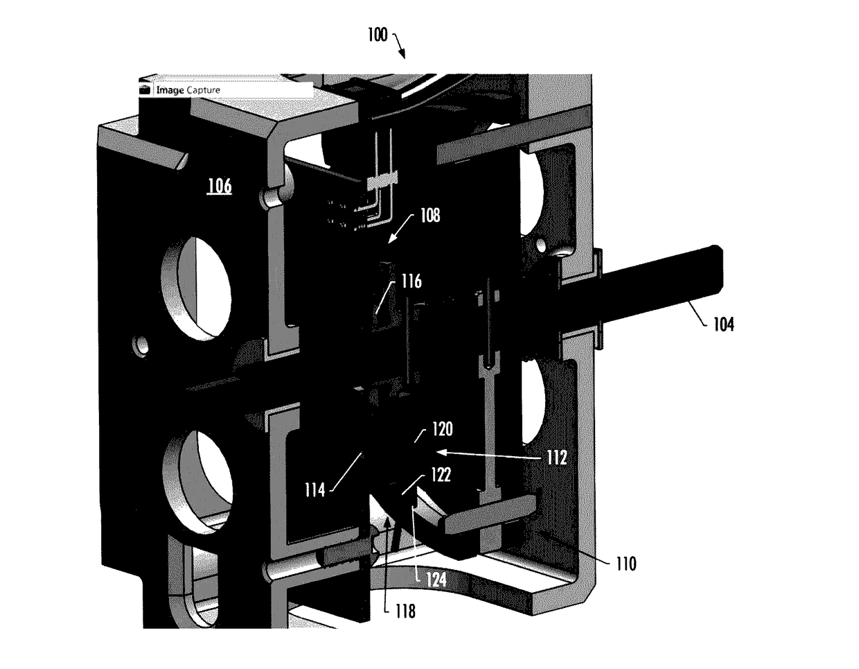
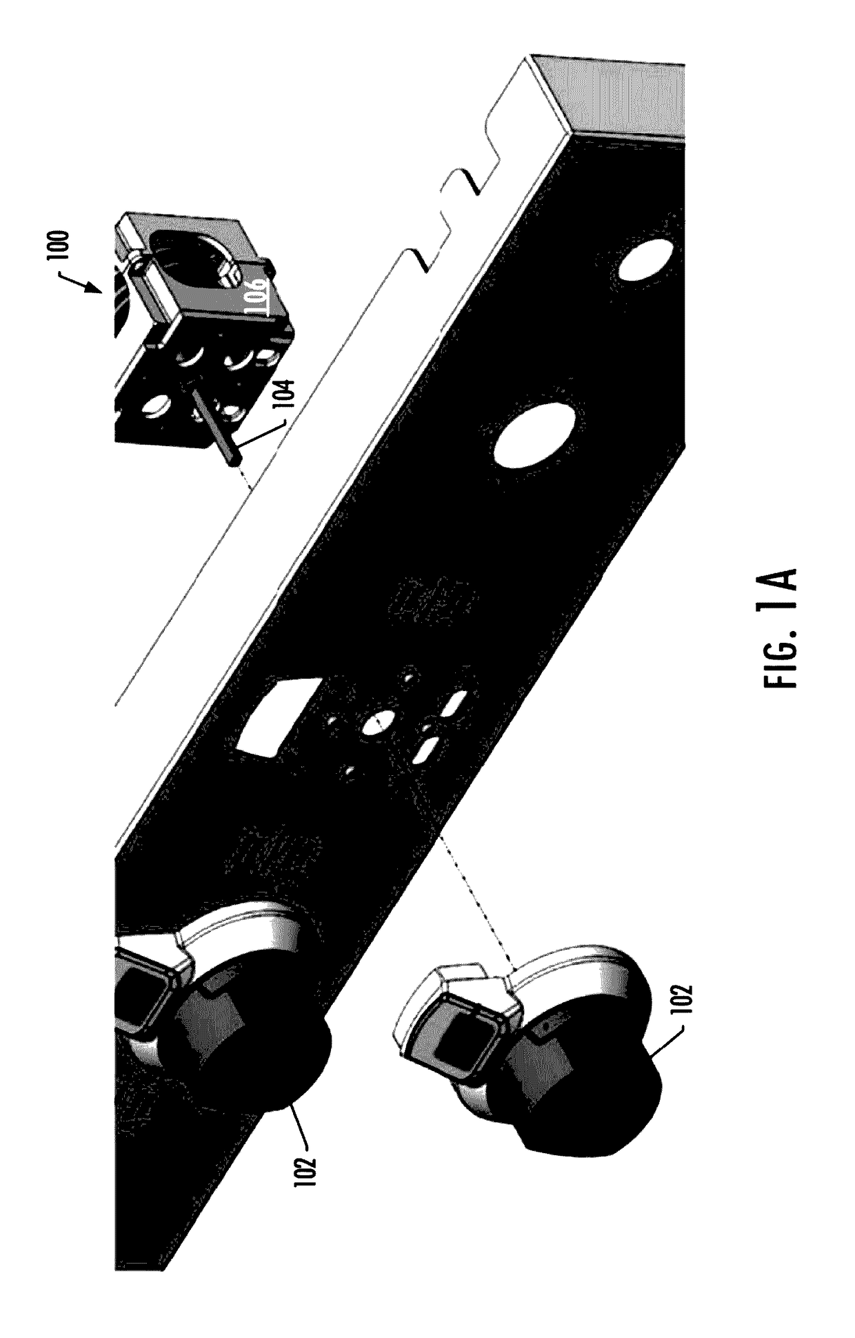
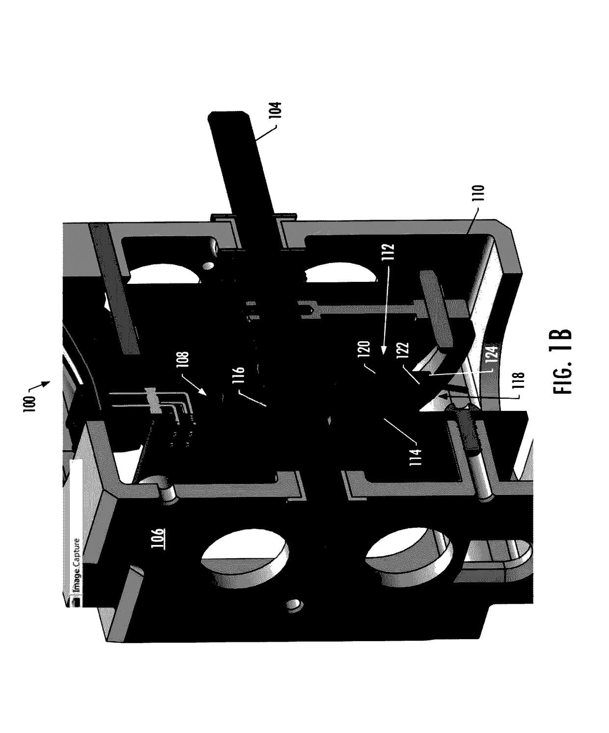
[0028]Some implementations of the present disclosure will now be described more fully hereinafter with reference to the accompanying drawings, in which some, but not all implementations of the disclosure are shown. Indeed, various implementations of the disclosure may be embodied in many different forms and should not be construed as limited to the implementations set forth herein; rather, these example implementations are provided so that this disclosure will be thorough and complete, and will fully convey the scope of the disclosure to those skilled in the art. For example, unless otherwise indicated, reference something as being a first, second or the like should not be construed to imply a particular order. Like reference numerals refer to like elements throughout. Also, for example, reference may be made herein to quantitative measures, values, relationships or the like. Unless otherwise stated, any one or more if not all of these may be absolute or approximate to account for a...


PUM


Abstract

A knob assembly is provided that includes a knob having a rotatable shaft, a rotatable first circuit board rigidly attached to the rotatable shaft, and a fixed second circuit board positioned near the first circuit board. The first circuit board includes an encoding portion configured to provide positioning data of the knob, and an eccentric rotating mass (ERM) motor mounted to the rotatable, first circuit board with a shaft of the ERM motor perpendicular to the rotatable shaft of the knob. The ERM motor is configured to produce and transfer vibration to the rotatable shaft of the knob. The second circuit board includes a sensor configured to determine a position of the first circuit board and thereby the knob at least in part from the positioning data provided by the encoding portion.

Description

TECHNOLOGICAL FIELD[0001]The present disclosure relates generally to appliances and, in particular, to an encoder for providing knob position sensing for an appliance.BACKGROUND[0002]Modern appliances may include appropriate components that provide for controlling and / or operating the appliance. In recent years, advancements and continued developments in sensor technology, encoder technology, and / or processing technology have enabled the implementation of sophisticated control units and / or controllers for home appliances. Various operational components of a home appliance may be controlled via a control unit and / or controller in response to various commands or user selections for controlling such components initiated through a control element such as, for example, an appliance knob.[0003]Traditional knobs utilize mechanical components (e.g., detents) to provide user feedback for positioning of the knob. These mechanical components may be fixed and prone to wear over time. Therefore,...

Claims


Application Information

Patent Timeline
IPC IPC(8): H03M1/22H01H19/54H01H19/14G05G1/10H01H19/02G01D5/26G01D5/02H03M1/00G01D5/14
CPCH01H19/02G05G1/10H01H19/14H01H19/54G01D5/26G01D5/14G01D5/02H03M1/00G05G1/08G05G5/03H01H2003/008
Inventor STOUFER, PAULJOSEFSSON, THOMASCARPENTER, KEVIN
Owner ELECTROLUX HOME PROD CORP NV
Why Eureka
Try Eureka