Flyback control mode-based controller and motor-controlling method thereof

a controller and control mode technology, applied in the field of motor control, can solve the problems of insufficient power generation, phase change of current, and inability to store energy through the feedback power in the single diode mode,

Inactive Publication Date: 2017-05-09
SHANGHAI DINGTE ELECTRICAL APPLICANCES CO LTD +1
View PDF1 Cites 3 Cited by
  • Summary
  • Abstract
  • Description
  • Claims
  • Application Information

AI Technical Summary

Benefits of technology

[0018]Another advantage of the invention is to provide a flyback control mode-based controller, wherein the control switch is a bi-directional conduction switch having one terminal connected to a terminal of the energy conversion circuit and another terminal connected to a terminal of the motor winding. Another terminal of the motor winding is connected another terminal of the energy conversion circuit. The control switch is selectively actuated to cut off or connected the energy conversion circuit from the motor winding.
[0019]Another advantage of the invention is to provide a flyback control mode-based controller, wherein the energy output circuit comprises a double-diode control. The energy output circuit comprises a power source U, a two switch transistors T1, T2, two flyback diodes D1, D2, and a motor winding L having two endpoints A, B. In particular, the switch transistor T1 has two terminals respectively connected to a positive terminal of the power source U and to the endpoint A where the terminal of the motor winding L is connected thereto. Another terminal of the motor winding L is connected the terminal of the switch transistor T2 at the endpoint B, wherein another terminal of the switch transistor T2 is connected to the negative terminal of the power source U. The cathode terminal of the flyback diode D1 is connected to the positive terminal of the power source U at the endpoint B. The cathode terminal of the flyback diode D2 is connected to the negative terminal of the power source U and the anode terminal of the flyback diode D2 is connected at the endpoint A. The control terminals of the switch transistors T1, T2 are connected to the control circuit. The energy conversion unit is connected between the endpoints A, B. The energy conversion unit comprises a control switch K and a capacitor C. A terminal of the control switch K is connected at the endpoint A and another terminal of the control switch K is connected to one terminal the capacitor C, wherein another terminal of the capacitor C is connected at the endpoint B.
[0020]Another advantage of the invention is to provide a flyback control mode-based controller, wherein for the single diode control mode, the energy output circuit, which is configured to include a power source U, two switch transistors T1, T2, two flyback diodes D1, D2, a capacitor C, and a motor winding L having two endpoints A, B. In particular, the switch transistor T1 has two terminals respectively connected to a positive terminal of the power source U and to the endpoint A where the terminal of the motor winding L is connected thereto. Another terminal of the motor winding L is connected to negative terminal of the power source U at the endpoint B. A terminal of the switch transistor T2 is connected to a terminal of the capacitor C and another terminal of the switch transistor T2 is connected at the endpoint B. Another terminal of the capacitor C is connected at the endpoint A. The cathode terminal of the flyback diode D1 is connected to the positive terminal of the power source U while the negative terminal of the power source U is connected at the endpoint A. The flyback diode D2 and the switch transistor T2 are connected in parallel, wherein the cathode terminal of the flyback diode D2 is connected to the capacitor C and the anode terminal of the flyback diode D2 is connected at the endpoint B.
[0021]Another advantage of the invention is to provide a flyback control mode-based controller, wherein when the attenuation is achieved via the energy conversion unit during the periodic oscillation, the current flow direction of the motor winding L will not be changed through the single control cycle.
[0022]Another advantage of the invention is to provide a flyback control mode-based controller, wherein for the single coil controlling mode, the energy output circuit, which is configured to include a power source U, two switch transistors T1, T2, two flyback diodes D1, D2, a capacitor C, two control switches K1, K2, and a motor winding L having two endpoints A, B. In particular, a terminal of the switch transistor T1 is connected to the positive terminal of the power source U while another terminal of the switch transistor T1 is connected to a terminal of the motor winding L at the endpoint A. Another terminal of the motor winding L is connected to a terminal of the switch transistor T2 at the endpoint B. Another terminal of the switch transistor T2 is connected to the negative terminal of the power source U. The cathode terminal of the flyback diode D1 is connected to the capacitor C and the anode terminal of the flyback diode D1 is connected at the endpoint B. The cathode terminal of the flyback diode D2 is connected at the endpoint A and the anode terminal of the flyback diode D2 is connected to the negative terminal of the power source U. A terminal of the control switch K1 is connected at the endpoint A and another terminal of the control switch K1 is connected to the capacitor C. A terminal of the control switch K2 is connected at the endpoint B and another terminal of the control switch K2 is connected to the negative terminal of the power source U. Another terminal of the capacitor C is connected to the negative terminal of the power source U.
[0023]Another advantage of the invention is to provide a flyback control mode-based controller, wherein the power output circuit is a star-shaped winding connection. The power output circuit is configured to have a power source U, a plurality of switch transistors T1, T2, T3, T4, T5, T6, two flyback diodes D1, D2, a capacitor C, a plurality of control switches K, K1, K2, an isolating diode D, and a plurality of three-phased motor windings L1, L2, L3. Terminals of the switch transistors T1, T3, T5 are connected to a terminal of the control switch K while another terminal of the control switch K is connected to the positive terminal of the power source U. Another terminals of the switch transistors T1, T3, T5 are connected to the terminals of three-phased motor windings L1, L2, L3. Another terminals of the three-phased motor winding L1, L2, L3 are connected with each other. Terminals of the switch transistors T2, T4, T6 are connected to the terminals of the switch transistors T1, T3, T5 while another terminals of the switch transistors T2, T4, T6 are connected to the negative terminal of the power source U. The cathode terminal of the flyback diode D1 is connected to the capacitor C and the control switch K1 in parallel connection. The anode terminal of the flyback diode D1 is connected to a terminal of the control switch K2. The cathode terminal of the flyback diode D2 is connected to the terminal of control switch K2 while the anode terminal of the flyback diode D2 is connected to the capacitor C and the control switch K2 in parallel connection. A terminal of the isolating diode D is connected to the switch control K1 and the flyback diode D2, while another terminal of the isolating diode D is connected to the switch transistors T1, T3, T5 and the control switch K in parallel connection.

Problems solved by technology

On the other hand, the energy cannot be stored through the feedback power in the single diode mode, wherein the energy saved at the diode will be discharged until it is used up.
At the same time, the phase of current is changing that the corresponding winding is initially connected and is insufficient to generate enough power to overcome the negative torque from the preceding winding.

Method used


Image

  • Flyback control mode-based controller and motor-controlling method thereof
  • Flyback control mode-based controller and motor-controlling method thereof
  • Flyback control mode-based controller and motor-controlling method thereof

Examples


embodiment 1

[0055] As shown in FIG. 4, the control switch of the motor or the conventional reluctance motor in FIG. 1 is a 2-way connection switch, wherein a terminal of the control switch is connected to a terminal of the energy conversion circuit and another terminal of the control switch is connected to a terminal of the motor winding. A second terminal of the motor winding is connected to the second terminal of the energy conversion circuit. Therefore, the control switch is actuated in an on and off manner to selectively connect and disconnect between the energy conversion circuit and the motor winding.

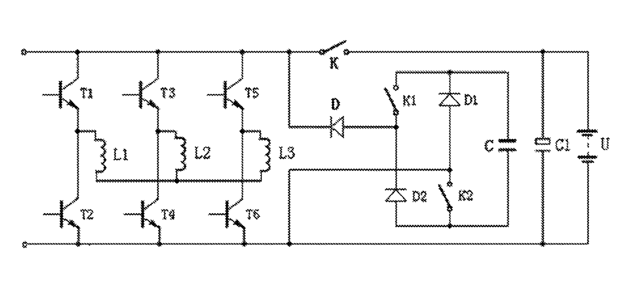
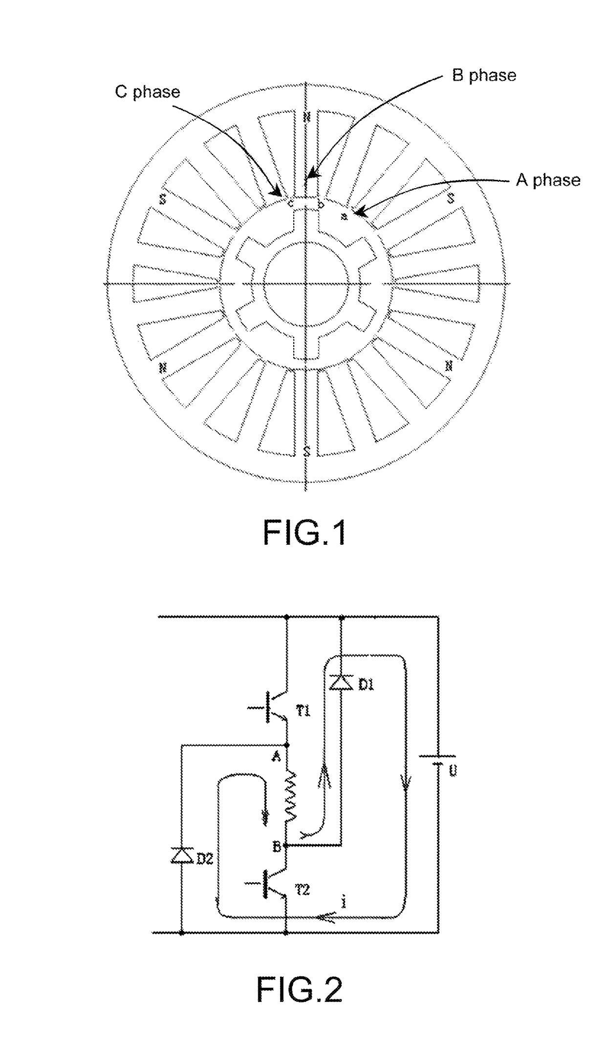
[0056]For the double diode control mode, the energy output circuit, which is configured to include a power source U, two switch transistors T1, T2, and two flyback diodes D1, D2, and a motor winding L having two endpoints A, B. In particular, the switch transistor T1 has two terminals respectively connected to a positive terminal of the power source U and to the endpoint A where the terminal ...

embodiment 2

[0061] As shown in FIG. 5, the control switch of the motor or the conventional reluctance motor in FIG. 1 is a 2-way connection switch, wherein a terminal of the control switch is connected to a terminal of the energy conversion circuit and another terminal of the control switch is connected to a terminal of the motor winding. A second terminal of the motor winding is connected to the second terminal of the energy conversion circuit. Therefore, the control switch is actuated in an on and off manner to selectively connect and disconnect between the energy conversion circuit and the motor winding.

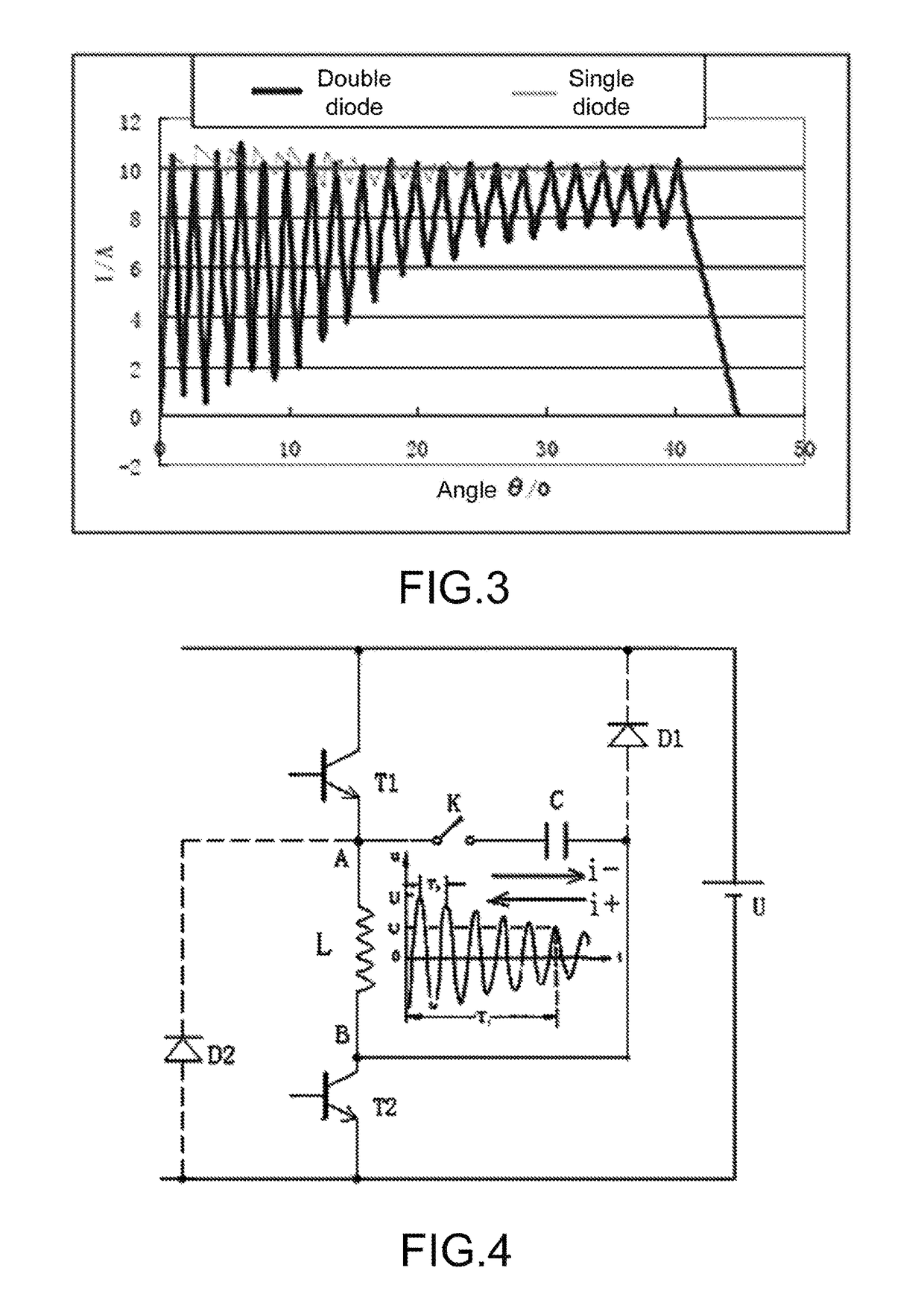
[0062]For the single diode control mode, the energy output circuit, which is configured to include a power source U, two switch transistors T1, T2, two flyback diodes D1, D2, a capacitor C, and a motor winding L having two endpoints A, B. In particular, the switch transistor T1 has two terminals respectively connected to a positive terminal of the power source U and to the endpoint A where th...

embodiment 3

[0066] For the permanent magnet motor that the permanent magnet is required, the current flow direction thereof is predetermined. Through the single control cycle (through the same yoke pole), the current flow direction cannot be changed, which is considered as the essential prerequisite for the energy conversion technology. When the attenuation is achieved via the energy conversion unit during the periodic oscillation, the current flow direction of the motor winding L will not be changed through the single control cycle.

[0067]For the permanent magnet motor, the wiring connection methods may be different, such that the corresponding structure of the energy conversion unit will be slightly different.

[0068]FIG. 7 illustrates the single coil controlling method, wherein the energy output circuit utilizes the single coil controlling method. The energy output circuit is configured to include a power source U, two switch transistors T1, T2, two flyback diodes D1, D2, a capacitor C, two con...


PUM


Abstract

A flyback control mode-based controller includes a power supply circuit, a position-checking circuit, a current-checking circuit, a control circuit, and a power output circuit. The power output circuit includes a controlled energy conversion unit. The energy conversion unit includes a control switch and an energy conversion circuit. The energy conversion circuit uses the capacitor C circuit, the inductor L circuit, or the LC circuit to connect parallelly or serially with an inductor in a motor winding L so as to form an oscillation circuit, such that periodic oscillations with attenuation are enabled by relying on the energy stored in the motor winding L. By applying the controller to motors having forward control mode or motors having flyback control mode, the current to be released by the motor during discharging can be repeated used, thereby achieving maximum energy conservation.

Description

CROSS REFERENCE OF RELATED APPLICATION[0001]This is a non-provisional application that claims priority to international application number PCT / CN2015 / 070247, international filing date Jan. 7, 2015, the entire contents of each of which are expressly incorporated herein by reference.NOTICE OF COPYRIGHT[0002]A portion of the disclosure of this patent document contains material which is subject to copyright protection. The copyright owner has no objection to any reproduction by anyone of the patent disclosure, as it appears in the United States Patent and Trademark Office patent files or records, but otherwise reserves all copyright rights whatsoever.BACKGROUND OF THE PRESENT INVENTION[0003]Field of Invention[0004]The present invention relates to a motor control, and more particularly to a flyback control mode-based controller and the motor-controlling method thereof.[0005]Description of Related Arts[0006]The operating principle for a power supplying system is that the power supplying s...

Claims


Application Information

Patent Timeline
Patent Type & Authority Patents(United States)
IPC IPC(8): H02K33/00H02P25/092
CPCH02P25/092
Inventor CHEN, XIPING
Owner SHANGHAI DINGTE ELECTRICAL APPLICANCES CO LTD
Why Eureka
Try Eureka