
Adjustable dispensing nozzle

a beverage dispenser and nozzle technology, applied in beverage vessels, household appliances, kitchen equipment, etc., can solve the problems of cumbersome means to adjust the distance between the beverage dispenser and the cup supporting surface of these known machines, and the housing is not large enough, so as to achieve the effect of simple and inexpensive means of adjusting

Active Publication Date: 2017-05-16
VERSUNI HLDG BV
View PDF35 Cites 2 Cited by
  • Summary
  • Abstract
  • Description
  • Claims
  • Application Information

AI Technical Summary

Benefits of technology

[0007]According to one aspect, the present invention provides a coffee producing machine, or more generally a beverage producing machine comprising simple, inexpensive means to adjust the distance between the rest surface on which the cup is placed and the beverage dispensing nozzle. The object of preferred embodiments of the invention is to provide a beverage producing machine having compact dimensions and still allowing the use of larger and smaller beverage collecting containers or cups.
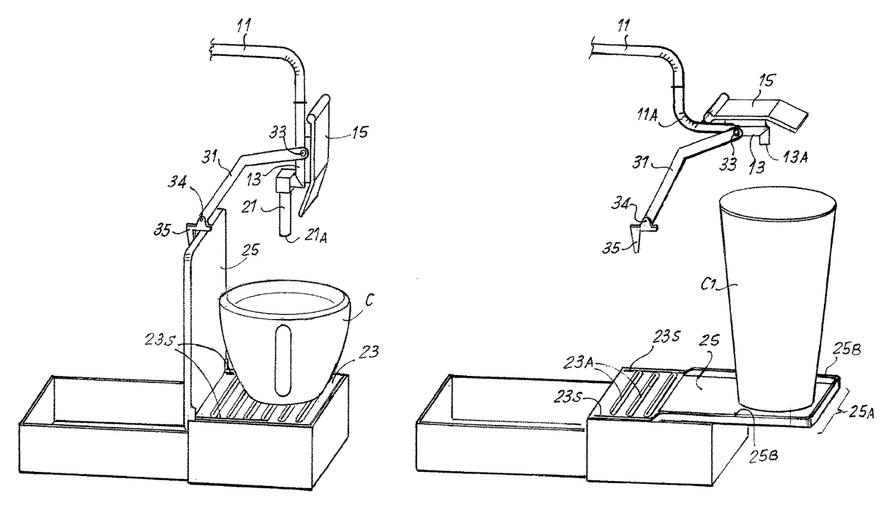
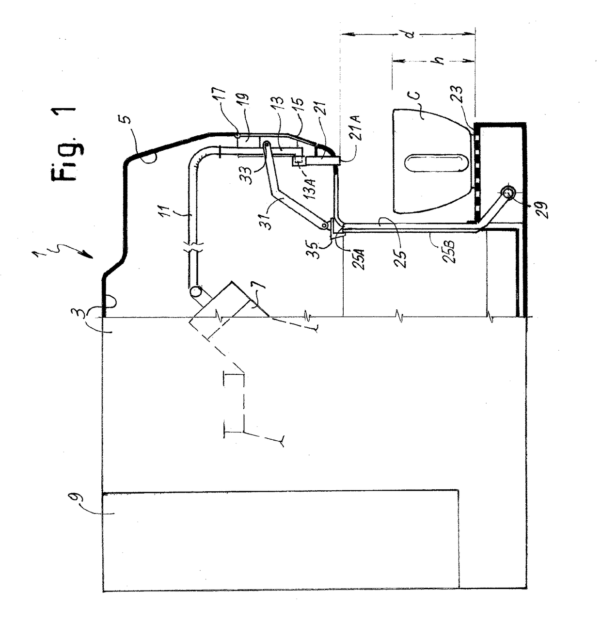
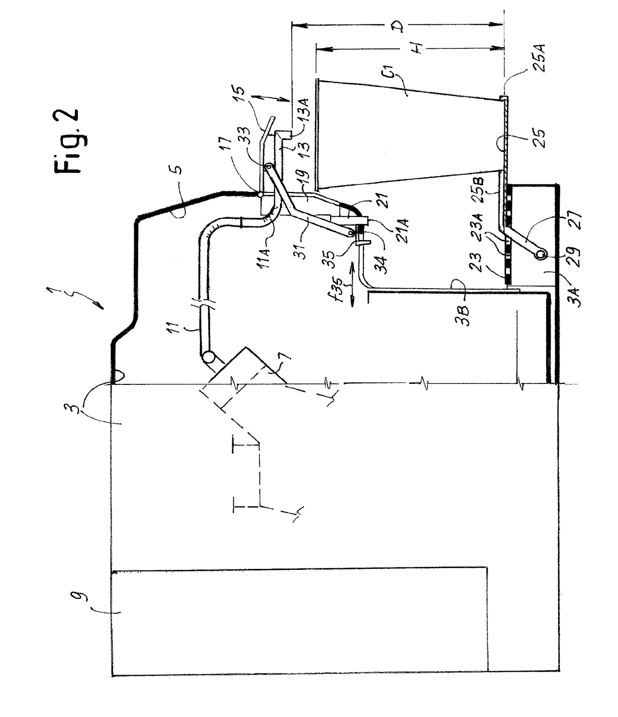
[0010]The arrangement is such that larger containers can be used by bringing the dispensing nozzle and the movable auxiliary surface in a position outside the footprint of the machine. The machine can therefore be designed with very small dimensions and in particular a small footprint. The machine is thus easy to transport and can also be located in areas where little room is available, e.g. a small kitchen. Nevertheless, the machine maintains the possibility of being adapted to dispense the beverage in a large cup or container, by simply tilting the dispensing nozzle and the movable auxiliary surface temporarily in an outwardly projecting position. When not required, the movable auxiliary surface and the dispensing nozzle can be tilted back in the respective rest positions, wherein they do not project outside the footprint of the machine.
[0016]To simplify the adjustment of the beverage producing machine, in some embodiments a mechanical connection is provided between the dispensing nozzle and the movable auxiliary surface. The mechanical connection can be designed such that acting on the dispensing nozzle only, both the dispensing nozzle and the movable auxiliary surface are moved, or vice-versa. In some embodiments a linkage can be provided, directly or indirectly connected to the dispensing nozzle and co-acting with the movable auxiliary surface. The linkage can be designed and arrange to cause the movable auxiliary surface to pivot from the rest position to the operative position when the beverage dispensing nozzle is moved from the first position to the second position. Moreover the linkage can be designed and arranged such that said linkage causes the beverage dispensing nozzle to tilt from the second position to the first position when the movable auxiliary surface is moved from the operative position to the rest position. In other embodiments, the linkage arrangement can be such that: when the user tilts the movable auxiliary surface from the rest position to the operative position, the dispensing nozzle is also moved from the first position to the second position; and when the user moves the dispensing nozzle from the second position to the first position, the linkage causes the reversal movement of the movable auxiliary surface from the operating position to the rest position. These arrangements make it possible to switch from one operating position to the other in a simpler manner e.g. using only one hand to act on the dispensing nozzle and alternatively on the movable auxiliary surface, making adjustment of the beverage producing machine easier and more user-friendly.

Problems solved by technology

Also in this case the adjusting mechanism is rather complex and expensive.
Moreover, the means to adjust the distance between the beverage dispensing nozzle and the cup supporting surface of these known machines are cumbersome and requires a rather large housing.

Method used


Image

  • Adjustable dispensing nozzle
  • Adjustable dispensing nozzle
  • Adjustable dispensing nozzle

Examples


Embodiment Construction

[0024]The following detailed description of the exemplary embodiments refers to the accompanying drawings. The same reference numbers in different drawings identify the same or similar elements. Additionally, the drawings are not necessarily drawn to scale. Also, the following detailed description does not limit the invention. Instead, the scope of the invention is defined by the appended claims.

[0025]Reference throughout the specification to “one embodiment” or “an embodiment” or “some embodiments” means that the particular feature, structure or characteristic described in connection with an embodiment is included in at least one embodiment of the subject matter disclosed. Thus, the appearance of the phrase “in one embodiment” or “in an embodiment” or “in some embodiments” in various places throughout the specification is not necessarily referring to the same embodiment(s). Further, the particular features, structures or characteristics may be combined in any suitable manner in one...


PUM


Abstract

A beverage producing machine is disclosed, comprising: a housing (3); a supporting surface (23) on which a beverage collecting container (C) can be placed; and a beverage dispensing nozzle (13) arranged above the supporting surface. The machine further comprises a movable auxiliary surface (25) which is combined to the supporting surface and is movable between an operating position and a rest position. In the operating position the movable auxiliary surface is parallel to the supporting surface. In the rest position the movable auxiliary surface is removed from the supporting surface. Moreover the dispensing nozzle (13) is movable between a first position for dispensing a beverage in a container placed on said supporting surface, and a second position for dispensing the beverage in a container placed on the movable auxiliary surface (25).

Description

[0001]This application is the U.S. National Phase application under 35 U.S.C. §371 of International Application No. PCT / IB2013 / 050388, filed on Jan. 16, 2013, which claims the benefit of U.S. Provisional Application No. 61 / 587,184 filed on Jan. 17, 2012. These applications are hereby incorporated by reference herein.TECHNICAL FIELD[0002]The present invention concerns beverage producing machines and in particular, though not exclusively, coffee producing machines.BACKGROUND ART[0003]Coffee producing machines are becoming increasingly popular and widely used household appliances.[0004]These machines are commonly used for the preparation of various kinds of coffee-based beverages, such as espresso coffee, fresh brew coffee (American coffee), cappuccino, “lattemacchiato” and so on. Depending upon the kind of beverage and wishes of the user, the beverage is collected in a smaller or larger container, such as an espresso cup, a large tea or coffee cup or the like. In order to allow the us...

Claims


Application Information

Patent Timeline
Patent Type & Authority Patents(United States)
IPC IPC(8): A47J31/46A47J31/44
CPCA47J31/46A47J31/4482
Inventor BALDO, MASSIMO
Owner VERSUNI HLDG BV
Learn More