
Remotely operable personal fall arrestment device and apparatus

a technology of personal fall arresting device and remote operation, which is applied in the direction of safety belts, vessel construction, fastening means, etc., can solve the problems of srl anchoring connector rings being problematic on a work si

Inactive Publication Date: 2017-05-30
LAY CRAIG D
View PDF16 Cites 9 Cited by
  • Summary
  • Abstract
  • Description
  • Claims
  • Application Information

AI Technical Summary

Benefits of technology

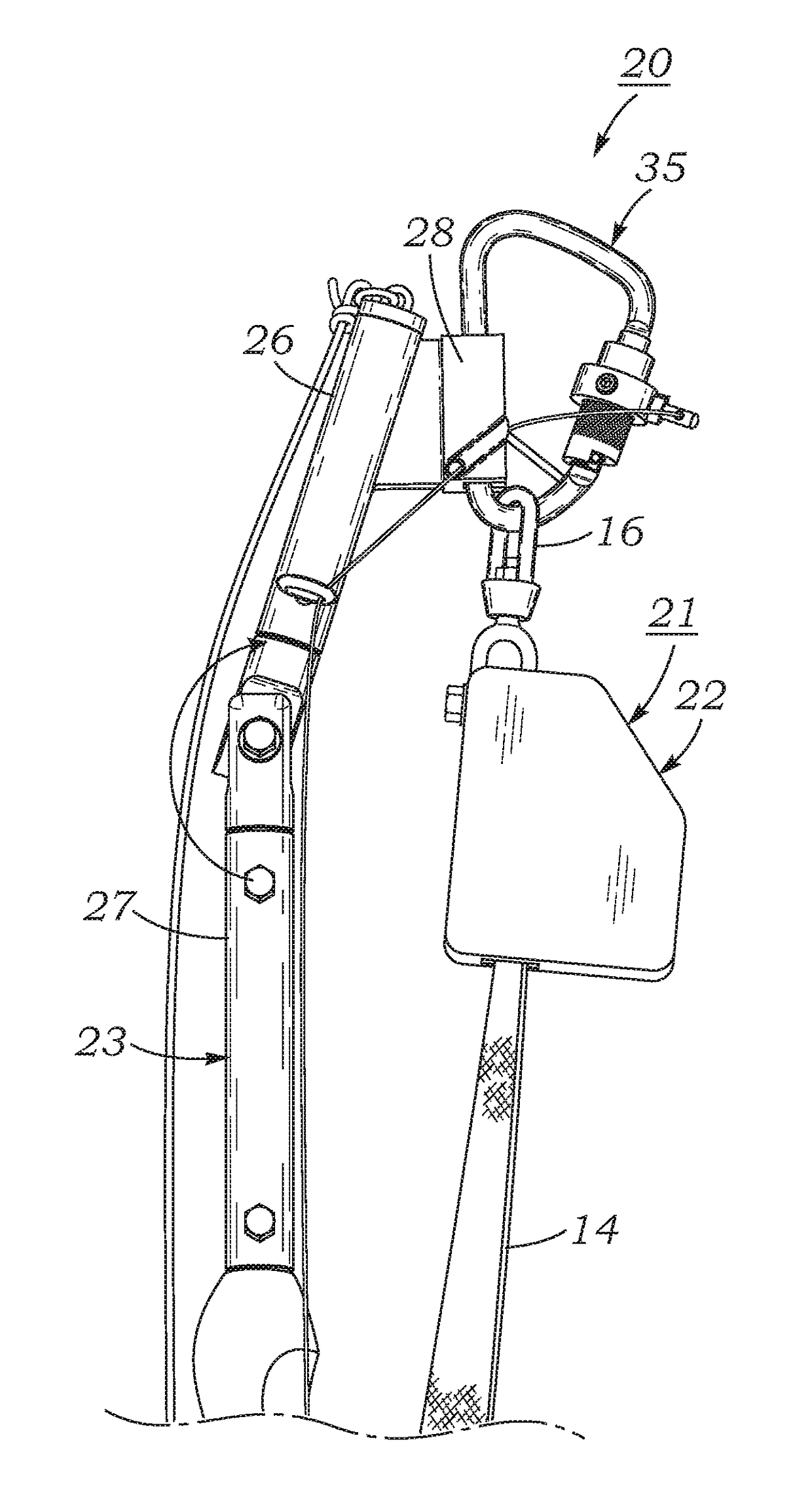
The present invention is a new fall arrestment apparatus that includes a self-retracting lanyard (SRL) and a remotely operable attachment device which allows the SRL to be easily attached and removed from an anchor member, such as a rebar, on a building or other structure. The attachment device is a pole with a saddle block clamp that can hold a carabiner connector ring, which is commonly used to support a safety harness worn by a workman to prevent accidents while working at high elevations. The technical effect of the invention is to provide a safer and easier way to prevent injury or death to workers who may accidentally fall while performing construction or maintenance tasks.

Problems solved by technology

However, there is a problem associated with the use of such systems in many practically encountered situations, as will now be described.
Since SRL anchoring connectors including carabiner type connector rings of the type described above must be secured to an anchoring member which is usually several feet or more above the head of a worker, it can be readily appreciated that securing an SRL anchoring connector ring to an elevated anchoring member at a work site may be problematic.

Method used


Image

  • Remotely operable personal fall arrestment device and apparatus
  • Remotely operable personal fall arrestment device and apparatus
  • Remotely operable personal fall arrestment device and apparatus

Examples


Embodiment Construction

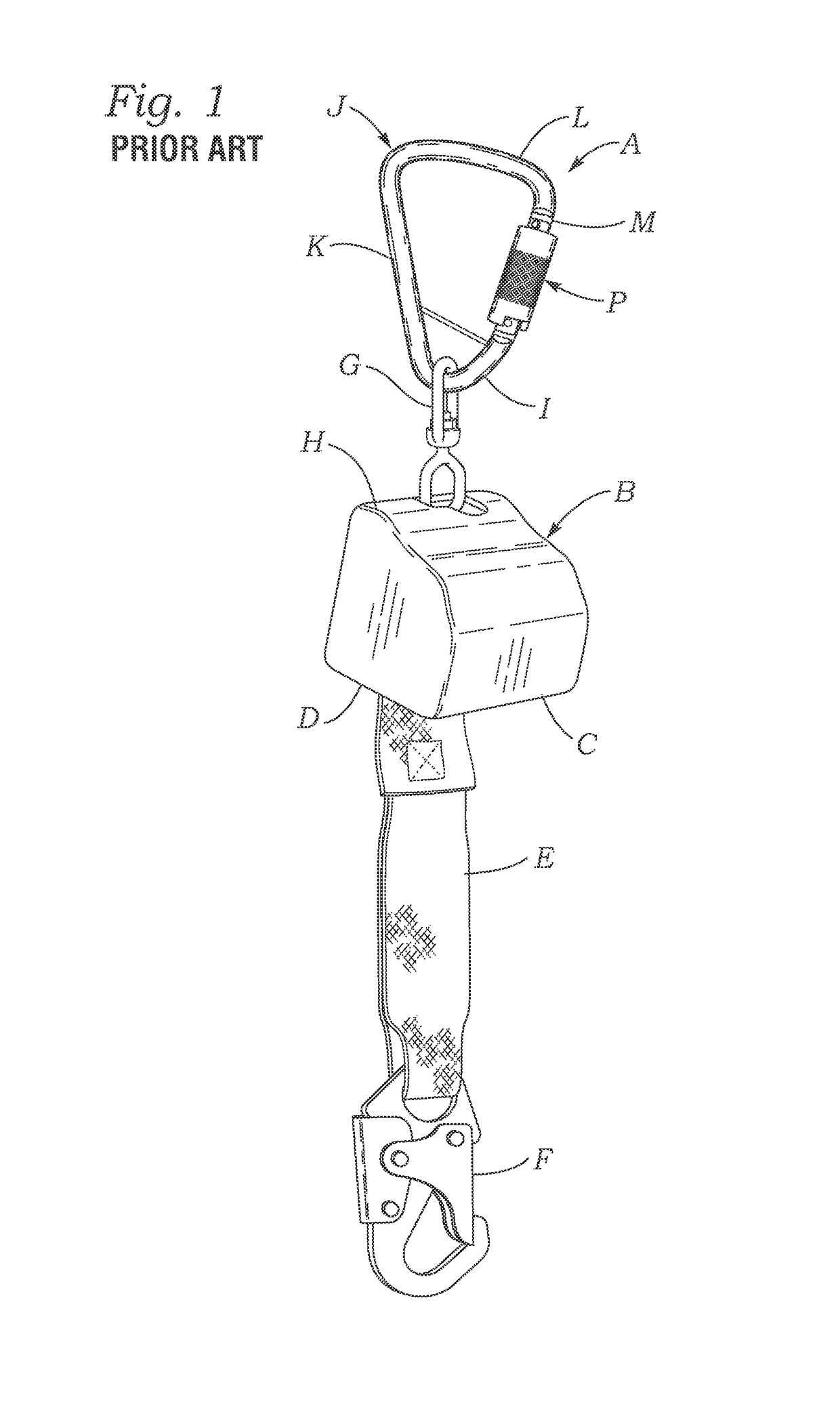
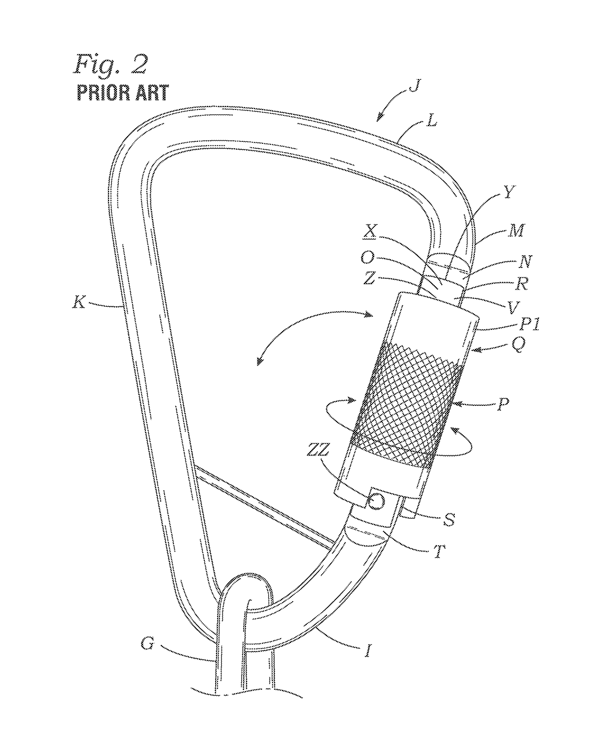
[0041]FIGS. 1 and 2 illustrate a prior art self-retracting lanyard (SRL) of the type which may be used in a remotely attachable personal fall arrestment apparatus according to the present invention. As shown in FIGS. 1 and 2, prior art SRL A includes a hollow block-shaped housing B that has protruding downwards through a slot D in a lower horizontal wall C of the housing a web-shaped lifeline E. An upper end of lifeline E is wound around a spool or reel of a deceleration device (not shown) located within housing B. Lifeline E has fastened to the lower end thereof a swivel snap ring F which is releasably attachable to a safety harness worn by a workman. The deceleration device within housing B allows a length of lifeline E to be paid out slowly, enabling lateral movement of a workman, but limits rapid vertical movement of a workman, such as in an accidental free fall, to a safe maximum distance.

[0042]As shown in FIGS. 1 and 2, SRL A includes a double-link swivel suspension connector ...


PUM


Abstract

A remotely attachable personal fall arrestment apparatus includes a self-retracting lanyard (SRL) having an upwardly protruding carabineer connector ring which has a gate link that is pivotable open to expose a downwardly protruding upper front hook link which is attachable to an anchor member such as a rebar or bolt eye located above a work site, and a lifeline retractably extendable downwardly from the SRL and releasably attachable to a safety body-harness worn by a worker The apparatus includes an SRL remote attachment device comprising a pole having an upper end which supports the connector ring, and a gate link operating mechanism that has a flexible cable deployed downwardly along the pole and having a lower end which may be grasped and tensioned to open the gate link and enable the hook link hook an anchor member, and released to allow a spring to close and lock the gate link.

Description

[0001]The present application claims priority of and to U.S. provisional application No. 61 / 929,056, filed Jan. 18, 2014, and incorporates by reference the entire contents of that application.BACKGROUND OF THE INVENTION[0002]A. Field of the Invention[0003]The present invention relates to safety apparatus for protecting against injurious or potentially fatal falls of workers such as construction workers or window washers working at elevations of more than a few feet above the ground. More particularly, the invention relates to a personal fall arrestment apparatus which includes a self-retracting lanyard (SRL) and a remotely operable attachment device for the SRL that enables the anchoring connector ring of the SRL to be remotely attachable by a workman to fixed anchor members located at elevations above the reach of a workman.[0004]B. Description of Background Art[0005]Federal and state safety regulations such as those promulgated by OSHA or Cal / OSHA routinely include requirements th...

Claims


Application Information

Patent Timeline
IPC IPC(8): F16B45/02B63B21/54A62B35/00
CPCA62B35/0068F16B45/025B63B21/54A62B35/0075A62B35/0093F16B45/021
Inventor LAY, CRAIG D.
Owner LAY CRAIG D
Learn More