Electric saw device

a saw blade and electric technology, applied in the direction of power driven reciprocating saws, saw blades, manufacturing tools, etc., can solve the problems of secondary tilt, motor becomes useless, and cut pieces between saw blades will become more serious, so as to facilitate maintenance and parts replacement

Inactive Publication Date: 2010-07-22
NEWSTAR ASIA
View PDF15 Cites 23 Cited by
  • Summary
  • Abstract
  • Description
  • Claims
  • Application Information

AI Technical Summary

Benefits of technology

[0013]The present invention is directed to an electric saw device, which has two saw blades, and realizes a rolling friction between the two saw blades to reduce a frictional force, such that the saw blades are not softened because of an acute temperature rise, and a cut piece is not easily clamped between the saw blades, so as to improve a cutting precision.
[0015]The present invention is still further directed to a structure for fixing a transmission shaft of a first saw blade of an electric saw device, in which the transmission shaft does not become loose when the saw blades are disassembled, so as to facilitate maintenance and parts replacement.
[0016]The electric saw device of the present invention includes a first saw blade and a second saw blade. The first and the second saw blade are respectively driven by a small transmission shaft and a large transmission shaft to rotate in opposite directions. A round rib is disposed on an inner end surface of the first saw blade, and at least three recessed holes are arranged in a top end surface of the round rib at equal angle intervals. A steel ball is accommodated in each of the recessed holes, and protrudes out of the recessed hole. Protruding ends of the steel balls urge against an inner surface of the second saw blade, so as to limit a distance between the first saw blade and the second saw blade, and form a rolling friction when the first and the second saw blades rotate in the opposite directions through rolling of the steel balls.
[0017]In the electric saw device, a first round protruding wall and a second protruding wall are disposed on an inner surface of the second saw blade. An inner diameter of the first round protruding wall is slightly greater than an outer diameter of the round rib of the first saw blade, and an outer diameter of the second round protruding wall is slightly smaller than an inner diameter of the round rib of the first saw blade. The first and the second round protruding walls prevent powder or small particles generated in cutting from entering a contact surface between the steel balls and the second saw blade.
[0018]In the electric saw device of the present invention, the small transmission shaft is driven to rotate by a power output shaft. An axial hole is arranged in the small transmission shaft, and a front end of the power output shaft is inserted in the axial hole. A contact surface between the power output shaft and the small transmission shaft is in a form that axial ribs are inserted in and tightly fitted with key ways. Further, a fixing screw is screwed in a tapped hole preset in a front end surface of the power output shaft, so as to tightly fix the first saw blade to the small transmission shaft, and prevent the small transmission shaft from getting loose.

Problems solved by technology

When the distance between the blade heads 42 and 43 of the first and the second saw blades 40 and 41 becomes greater, the problem of the cut piece between the saw blades will become more serious, which may eventually make a motor become useless because the motor is burned due to overload.
Besides, as the fixing is based on the threads, a secondary tilt may occur.
Therefore, the problems that the saw blades 50 and 51 wiggle, jump, or damage the saw teeth become more serious, thus resulting in an unstable current and overload of the electric motor, and shortening the service life of the electric motor.

Method used


Image

  • Electric saw device
  • Electric saw device
  • Electric saw device

Examples


Embodiment Construction

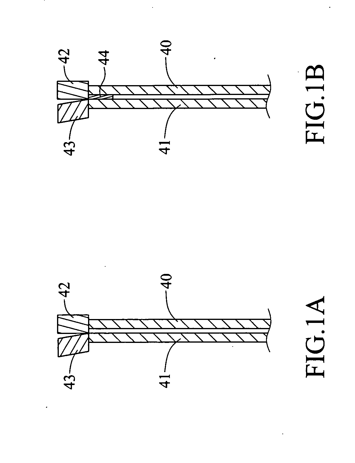
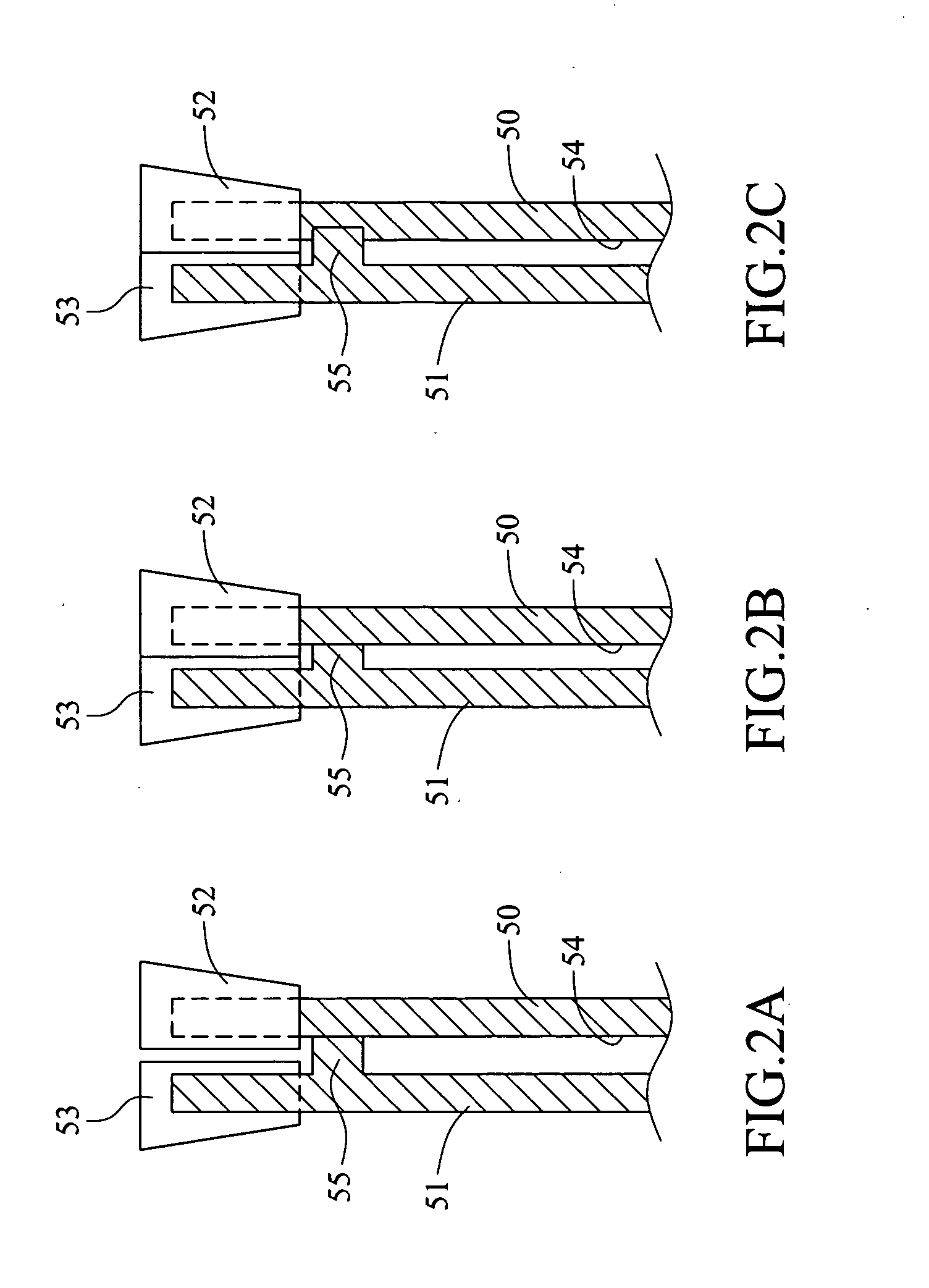
[0033]To solve the problems of the cutting precision and life of the two saw blades, the fundamental method is to reduce the frictional force so that the saw blades do not deform because of high temperature, and to prevent the saw blades from tilting after assembly. Therefore, the inventor proposes the present invention. The present invention reduces the frictional force between the two saw blades to prevent a cutting piece from being sandwiched between the saw blades, and makes the saw blades be assembled stably, so as to improve the cutting precision and prolong the life of the saw blades. The structure and efficacy of the present invention will be illustrated in detail in the following with reference to the accompanying drawings.

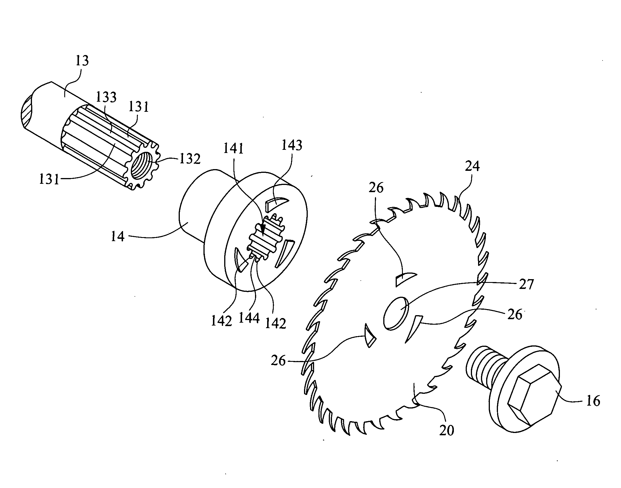
[0034]FIG. 4 is a structural view of an electric saw device. Referring to FIG. 4, in the electric saw device 1, two gears 11 and 12 are driven by a motor power shaft 10 to rotate at a same speed in opposite directions. The gear 11 is fixed to a power outp...


PUM

PropertyMeasurementUnit
distanceaaaaaaaaaa
distanceaaaaaaaaaa
heightaaaaaaaaaa

Abstract

An electric saw device includes a first saw blade and a second saw blade. The first and the second saw blades are respectively driven by a small transmission shaft and a large transmission shaft to rotate in opposite directions. A round rib is disposed on an inner end surface of the first saw blade, and at least three recessed holes are arranged in a top end surface of the round rib at equal angle intervals. A steel ball is accommodated in each of the recessed holes, and protrudes out of the recessed hole. Protruding ends of the steel balls urge against an inner surface of the second saw blade, so as to limit a distance between the first saw blade and the second saw blade, and form a rolling friction when the first and the second saw blade rotate in the opposite directions. Further, a power output shaft of the electric saw device is joined with the small transmission shaft of the first saw blade through a key connection structure, so as to ensure that the saw blades do not tilt after installation.

Description

BACKGROUND OF THE INVENTION[0001]1. Field of Invention[0002]The present invention relates to an electric saw device having two saw blades, which realizes a rolling friction between the two saw blades to reduce a frictional force, and uses a key connection between transmission shafts of the saw blades and a power output shaft to improve stability of the connection.[0003]2. Related Art[0004]In an electric saw device having two saw blades, a first saw blade and a second saw blade are driven to rotate simultaneously in opposite directions to saw a work piece. FIG. 1a is a structural view of two saw blades of the prior art. As shown in FIG. 1a, blade heads 42 and 43 of the first and the second saw blades 40 and 41 are in contact with each other. In a cutting process, the blade heads 42 and 43 may generate a high temperature due to the contact friction. Further, the blade heads 42 and 43 of the two saw blades 40 and 41 may collide with each other easily, so the blade heads 42 and 43 will ...

Claims


Application Information

Patent Timeline
Patent Type & Authority Applications(United States)
IPC IPC(8): B23D45/16B23D45/00B23D45/10
CPCB23D45/10B27B5/32B23D61/025B23D47/126Y10T83/9324Y10T83/9374Y10T83/9379
Inventor CHENG, CHUNG-CHI
Owner NEWSTAR ASIA
Why Eureka
Try Eureka