
Extended OLED operational lifetime through phosphorescent dopant profile management

Active Publication Date: 2017-05-30
RGT UNIV OF MICHIGAN
View PDF82 Cites 29 Cited by
  • Summary
  • Abstract
  • Description
  • Claims
  • Application Information

AI Technical Summary

Benefits of technology

The present invention provides an organic light emitting device with a first emissive layer comprising an electron transporting compound and a phosphorescent emissive dopant compound, wherein the phosphorescent emissive dopant compound has a concentration gradient that varies from the cathode side of the first emissive layer to the anode side of the emissive layer. The device also includes a second emissive layer, which may have a different concentration gradient or a step-wise form. The device may also have an interconnecting layer between the first and second emissive layers. The invention provides an organic light emitting device with improved efficiency and a longer lifespan compared to devices with a uniform concentration of the phosphorescent emissive dopant compound in the emissive layer.

Problems solved by technology

Unfortunately, the blue sub-pixels in OLED displays employ fluorescent OLEDs due to the short operational lifetime in analogous PHOLEDs as reported by Tsujimura, T. OLED Displays: Fundamentals and Applications.

Method used


Image

  • Extended OLED operational lifetime through phosphorescent dopant profile management
  • Extended OLED operational lifetime through phosphorescent dopant profile management
  • Extended OLED operational lifetime through phosphorescent dopant profile management

Examples


Embodiment Construction

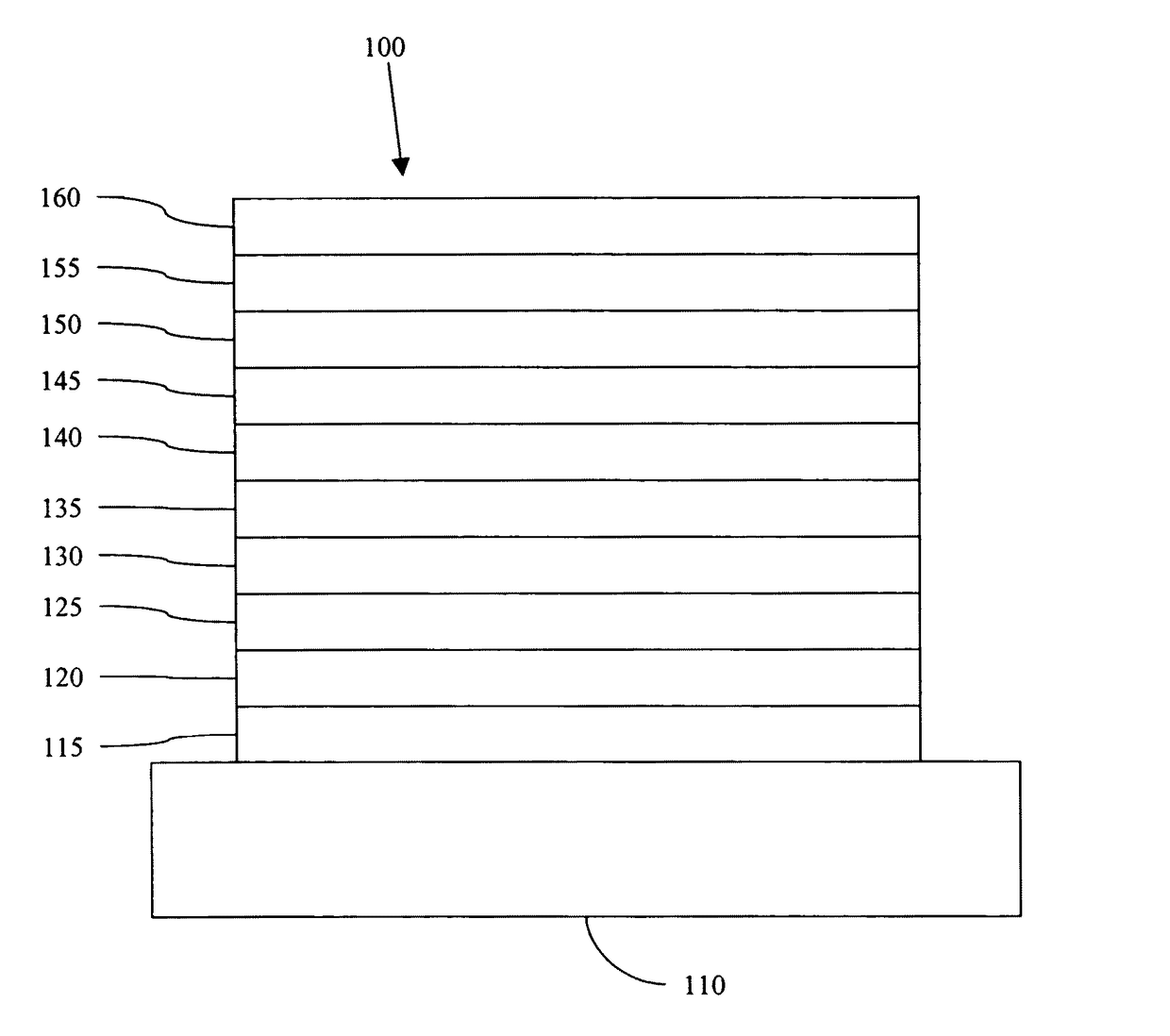
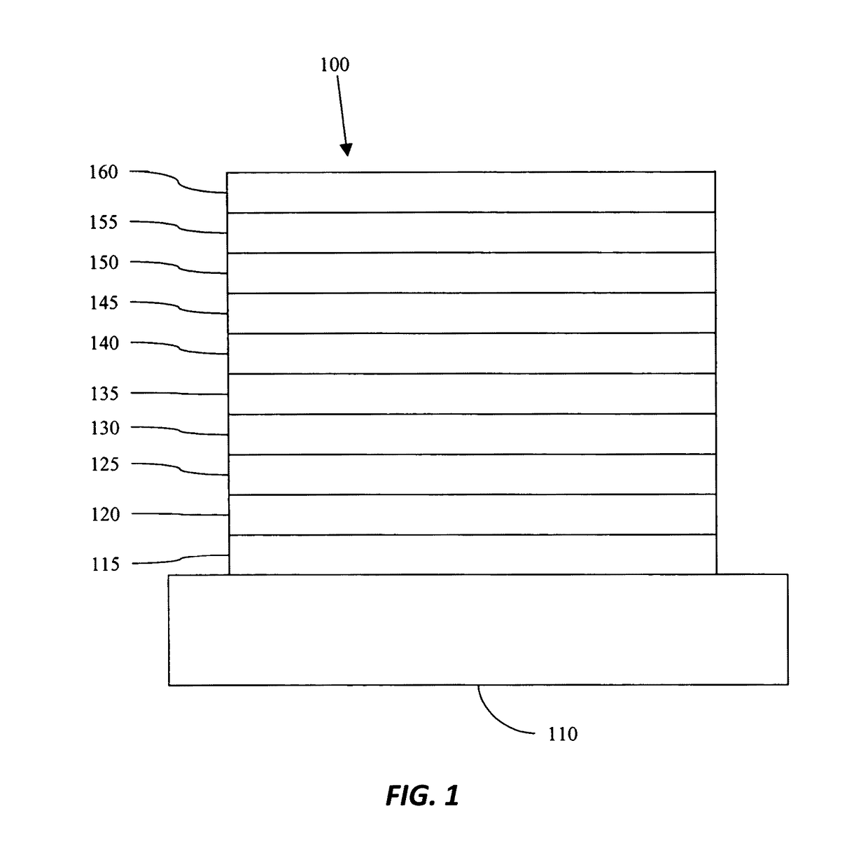
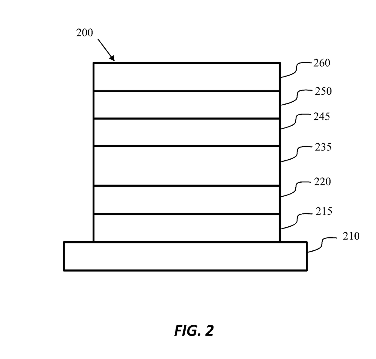
[0065]Generally, an OLED comprises at least one organic layer disposed between and electrically connected to an anode and a cathode. When a current is applied, the anode injects holes and the cathode injects electrons into the organic layer(s). The injected holes and electrons each migrate toward the oppositely charged electrode. When an electron and hole localize on the same molecule, an “exciton,” which is a localized electron-hole pair having an excited energy state, is formed. Light is emitted when the exciton relaxes via a photoemissive mechanism. In some cases, the exciton may be localized on an excimer or an exciplex. Non-radiative mechanisms, such as thermal relaxation, may also occur, but are generally considered undesirable.

[0066]The initial OLEDs used emissive molecules that emitted light from their singlet states (“fluorescence”) as disclosed, for example, in U.S. Pat. No. 4,769,292, which is incorporated by reference in its entirety. Fluorescent emission generally occur...


PUM


Abstract

This disclosure relates, at least in part, an organic light emitting device, which in some embodiments comprises an anode; a cathode; a first emissive layer disposed between the anode and the cathode, the first emissive layer comprising an electron transporting compound and a phosphorescent emissive dopant compound; and wherein the phosphorescent emissive dopant compound has a concentration gradient, in the emissive layer, which varies from the cathode side of the first emissive layer to the anode side of the emissive layer.

Description

CROSS-REFERENCE TO RELATED APPLICATIONS[0001]This application claims priority to, and the benefit of, U.S. Provisional Patent Application No. 61 / 916,914 filed Dec. 17, 2013; U.S. Provisional Patent Application No. 61 / 929,354 filed Jan. 20, 2014; U.S. Provisional Patent Application No. 61 / 974,789 filed Apr. 3, 2014; and U.S. Provisional Patent Application No. 62 / 040,019 filed Aug. 21, 2014, all of which are incorporated herein by reference herein in their entireties.STATEMENT REGARDING FEDERALLY SPONSORED RESEARCH OR DEVELOPMENT[0002]This invention was made with U.S. Government support under Contract No. DE-SC0001013-sub-K113153 awarded by the Department of Energy. The government may have certain rights in this invention.[0003]The claimed invention was made by, on behalf of, and / or in connection with one or more of the following parties to a joint university corporation research agreement: Regents of the University of Michigan, Princeton University, The University of Southern Califor...

Claims


Application Information

Patent Timeline
Patent Type & Authority Patents(United States)
IPC IPC(8): H01L33/02H01L51/50H01L51/00H10K99/00
CPCH01L51/5024H01L51/0072H01L51/0085H01L51/5004H01L51/5016H01L51/5072H01L51/5088H01L2251/5346H01L2251/5384H10K85/6572H10K85/342H10K50/11H10K2101/40H10K2101/10H10K2101/80H10K2101/90H10K50/12H10K50/16H10K50/17
Inventor FORREST, STEPHEN R.ZHANG, YIFAN
Owner RGT UNIV OF MICHIGAN
Learn More