Circuit module having surface-mount pads on a lateral surface for connecting with a circuit board

a circuit board and surface mount technology, applied in the field of board design, can solve the problems of reducing the size of the system, affecting the layout of the circuit board, and occupying a large space for the connector, so as to reduce the connecting space

Active Publication Date: 2017-05-30
CYNTEC
View PDF1 Cites 0 Cited by
  • Summary
  • Abstract
  • Description
  • Claims
  • Application Information

AI Technical Summary

Benefits of technology

[0008]One objective of the present invention is to provide a circuit module for connecting to a circuit board or a motherboard by using surface-mounting pads on a lateral surface of the circuit module so as to reduce the connecting space between the circuit module and the circuit board.

Problems solved by technology

As more and more components or boards are integrated into a system, such as a server, reducing the size of the system while increasing the electrical performance of the system becomes a bottleneck of designing the overall system.
Conventionally, connectors are used for connecting different boards; however, the connectors take up a large space in both the circuit module and the circuit board to which the circuit module is connected to.
In addition, the connectors will block usable layout area due to the fact that the connectors are usually mounted on the boards by using through-hole pins.
In addition, the connectors that are used to connect the circuit module and the circuit board or motherboard will degrade the electrical performance such that the frequency of the signals passing through the connectors must be lowered in order to maintain reliable operations.

Method used


Image

  • Circuit module having surface-mount pads on a lateral surface for connecting with a circuit board
  • Circuit module having surface-mount pads on a lateral surface for connecting with a circuit board
  • Circuit module having surface-mount pads on a lateral surface for connecting with a circuit board

Examples


Embodiment Construction

[0035]The detailed explanation of the present invention is described as following. The described preferred embodiments are presented for purposes of illustrations and description, and they are not intended to limit the scope of the present invention.

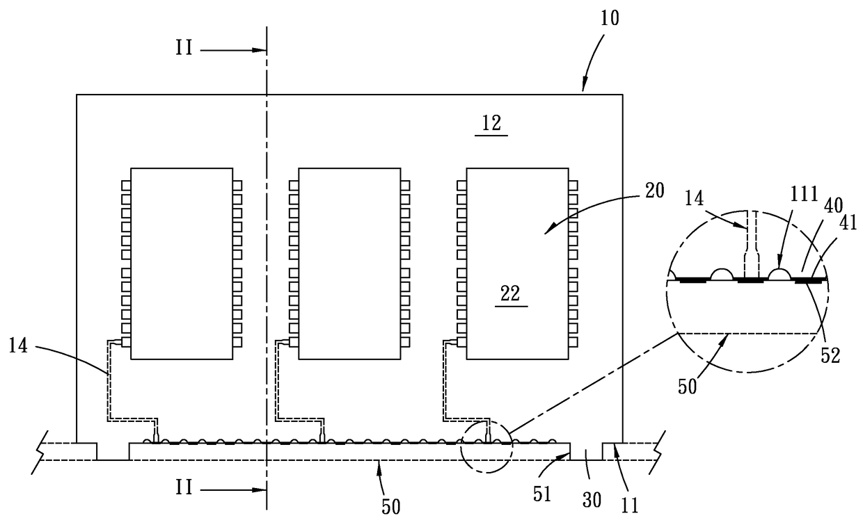
[0036]The following embodiments disclose a circuit module for connecting to a circuit board, wherein the circuit module comprises a substrate having a top surface, a bottom surface and a lateral surface connecting the top surface and bottom surface, wherein at least one electrical component is disposed on the top or bottom surface and a plurality of surface-mount pads are disposed on the lateral surface of the substrate for electrically connecting to corresponding pads on the circuit board.

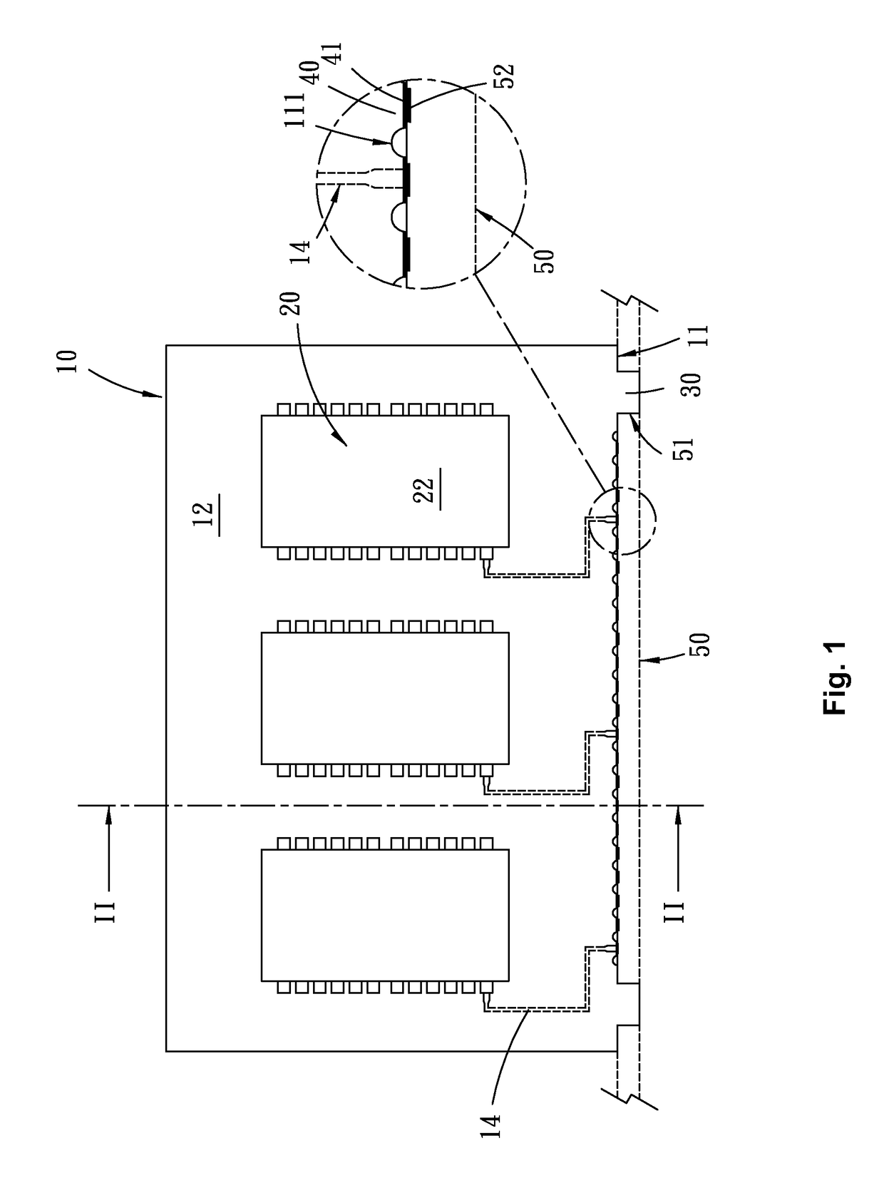
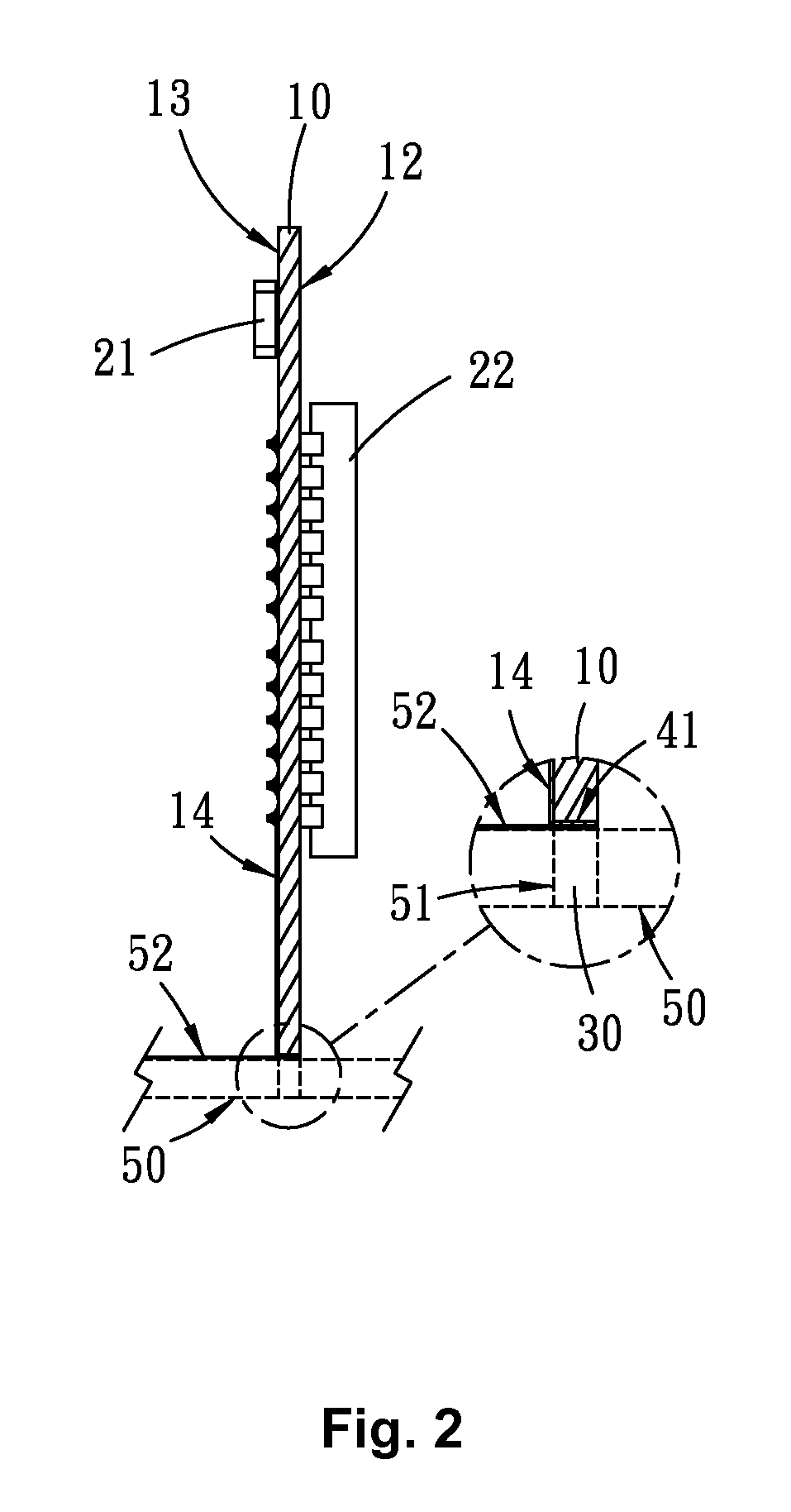
[0037]Please refer to FIG. 1 and FIG. 2, which illustrates a front view and a sectional view of the structure of a surface-mount type circuit module in one embodiment of the present invention, wherein the surface-mount type circuit module comprises: a ...


PUM


Abstract

A circuit module for connecting to a circuit board is disclosed, the circuit module for connecting to a circuit board, wherein the circuit module comprises a substrate having a top surface, a bottom surface and a lateral surface connecting the top surface and bottom surface, wherein at least one electrical component is disposed on the top or bottom surface and a plurality of surface-mount pads are disposed on the lateral surface of the substrate for electrically connecting to corresponding pads on the circuit board.

Description

BACKGROUND OF THE INVENTION[0001]I. Field of the Invention[0002]the present invention relates to a board design, and in particularly, to a circuit module design for connecting with a circuit board.[0003]II. Description of the Prior Art[0004]As an electronic system becomes smaller and smaller, the overall system level design must consider size requirements as well as usable layout areas in the circuit board or the circuit modules that will be connected to the circuit board. Usually, there is a motherboard in a system on which multiple circuit modules are attached to the motherboard. In order to save space, the circuit module stands on the mother board using a lateral surface of the circuit module, wherein electronic devices are disposed or mounted on the top or bottom surface of the circuit module.[0005]when designing a system with multiple circuit boards (PCB), the interconnection between a circuit module and the motherboard is very important. As more and more components or boards a...

Claims


Application Information

Patent Timeline
Patent Type & Authority Patents(United States)
IPC IPC(8): H05K7/10H05K3/36H05K7/12H05K1/11
CPCH05K3/366H05K1/117H05K2201/09063H05K2201/09172H05K2201/1034H05K2201/10295H05K1/0203H05K1/181H05K2201/10454
Inventor LU, BAU-RU
Owner CYNTEC
Why Eureka
Try Eureka