Electrode structure and the corresponding electrical component using the same and the fabrication merhod thereof

a technology of electrical components and electrodes, applied in the direction of transformers/inductance coils/windings/connections, inductances with magnetic cores, inductances, etc., can solve the problems of affecting the yield rate of electrical components in manufacturing factories, affecting the size and reliability of electrode structures, and affecting the yield rate of electrical components. , to achieve the effect of reducing the connecting spa

Active Publication Date: 2019-01-22
CYNTEC
View PDF5 Cites 0 Cited by
  • Summary
  • Abstract
  • Description
  • Claims
  • Application Information

AI Technical Summary

Benefits of technology

[0008]One objective of the present invention is to provide a circuit module for connecting to a circuit board or a motherboard by using surface-mounting pads on a lateral surface of the circuit module so as to reduce the connecting space between the circuit module and the circuit board.

Problems solved by technology

As an electrical component or an electronic device becomes smaller and smaller, the size and the reliability of the electrode structure becomes a bottleneck considering the electrical performance and the reliability of the electrical component.
A lead frame is usually welded to the terminals of the electrical component; however, the size of the lead frame normally takes quite a large space for an electrical component in a small foot print and therefore, the lead frame is not suitable for being used as an electrode for certain electrical components or electronic devices that requires a smaller size.
The resistance of an electrode created by conventional electroplating may vary very much, which degrades electrical performance in certain applications or even affect the yield rate of the electrical components in manufacturing factory.
On the other hand, chemical plating can cause a short circuit when the material of the plating spreads into certain unwanted areas.

Method used


Image

  • Electrode structure and the corresponding electrical component using the same and the fabrication merhod thereof
  • Electrode structure and the corresponding electrical component using the same and the fabrication merhod thereof
  • Electrode structure and the corresponding electrical component using the same and the fabrication merhod thereof

Examples


Embodiment Construction

[0041]The detailed explanation of the present invention is described as following. The described preferred embodiments are presented for purposes of illustrations and description, and they are not intended to limit the scope of the present invention.

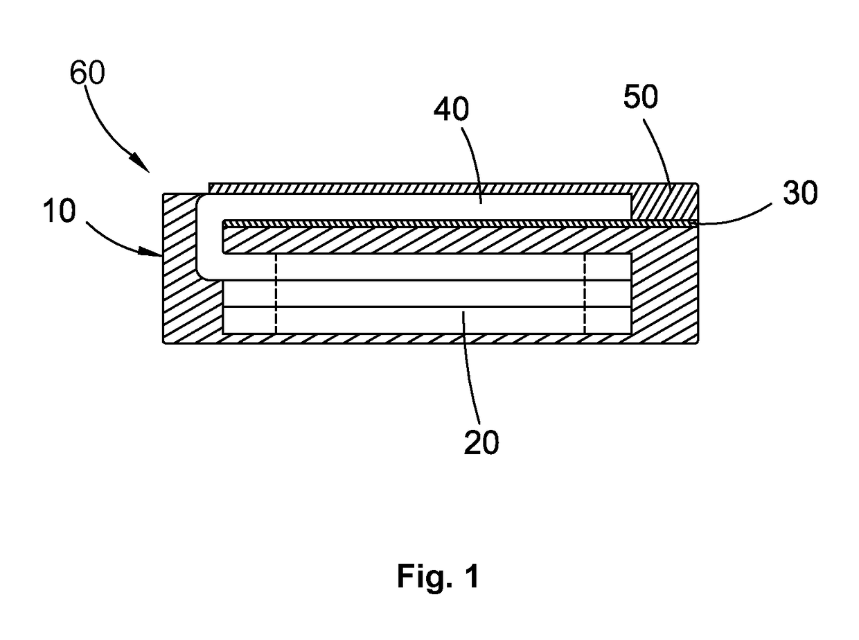
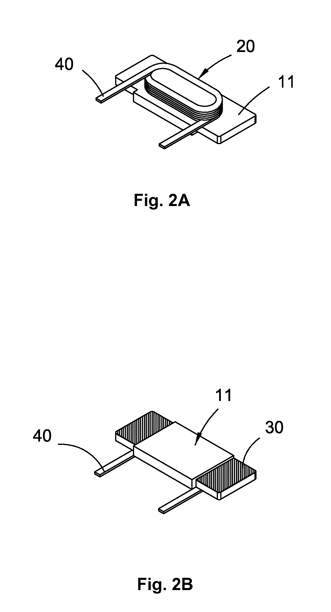
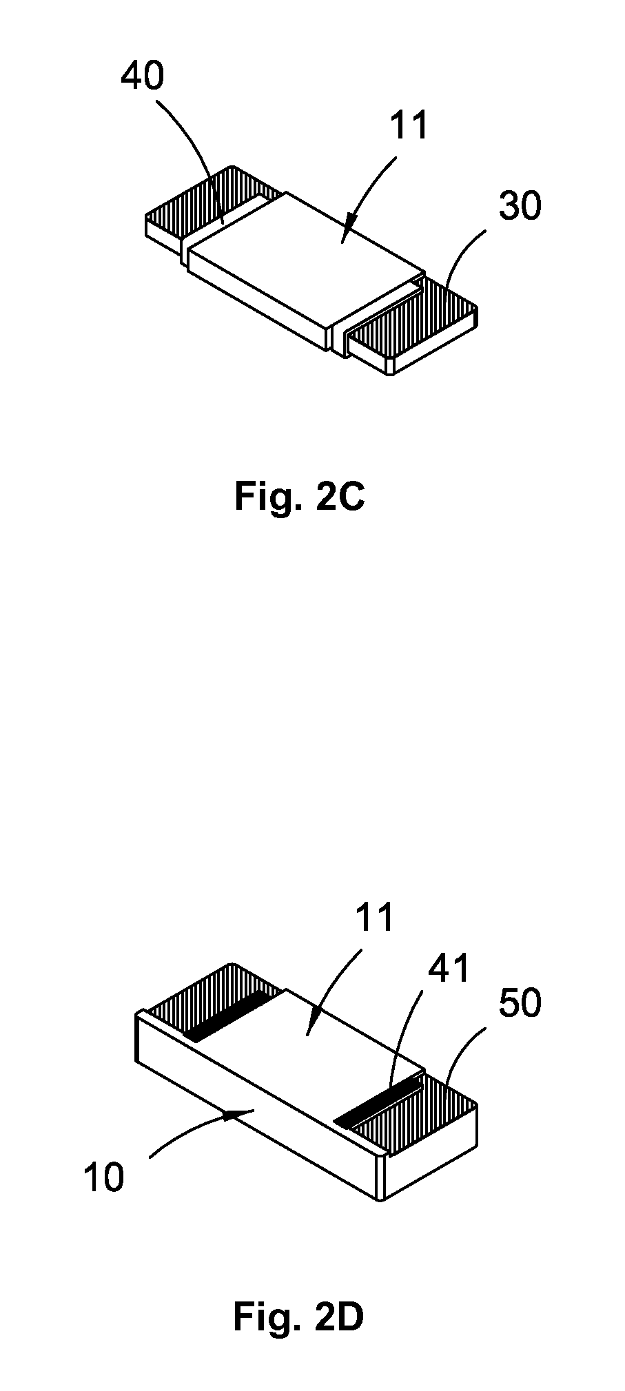
[0042]The following embodiments disclose an electrical component, wherein the electrical component comprises: a body and an electrode structure disposed on a first surface of the body, wherein the electrode structure comprises an inner metal layer and an outer metal layer, wherein a terminal of a conductive element of the electrical component is disposed between the inner metal layer and the outer metal layer, wherein the terminal of the conductive element of the electrical component is electrically connected to the inner metal layer and the outer metal layer for electrically connecting with an external circuit.

[0043]Please refer to FIG. 1, which illustrates a cross-sectional view of an electrode structure of an electrical component acco...


PUM

PropertyMeasurementUnit
thicknessaaaaaaaaaa
thicknessaaaaaaaaaa
thicknessaaaaaaaaaa

Abstract

An electrical component is disclosed, wherein the electrical component comprises: a body and an electrode structure disposed on a first surface of the body, wherein the electrode structure comprises an inner metal layer and an outer metal layer, wherein a terminal of a conductive element of the electrical component is disposed between the inner metal layer and the outer metal layer, wherein the terminal of the conductive element of the electrical component is electrically connected to the inner metal layer and the outer metal layer for electrically connecting with an external circuit.

Description

CROSS-REFERENCES TO RELATED APPLICATIONS[0001]This application claims the benefit of U.S. Provisional Patent Application No. 61 / 990,735 filed on May 9, 2014, which is hereby incorporated by reference herein and made a part of specification.BACKGROUND OF THE INVENTION[0002]I. Field of the Invention[0003]the present invention relates to an electrical component, and in particularly, to the electrodes of the electrical component.[0004]II. Description of the Prior Art[0005]As an electrical component or an electronic device becomes smaller and smaller, the size and the reliability of the electrode structure becomes a bottleneck considering the electrical performance and the reliability of the electrical component. The electrodes are used to connect the electrical component to an external circuit such as a printed circuit board (PCB), and terminals of the conductive elements of the electrical component are electrically connected to corresponding electrodes such as surface-mount pads for so...

Claims


Application Information

Patent Timeline
Patent Type & Authority Patents(United States)
IPC IPC(8): H01F17/04H01F41/10H01F27/02H01F27/29H01F41/12H01F27/28
CPCH01F27/292H01F17/045H01F41/12H01F41/10Y10T29/49075H01F27/2847
Inventor LEE, CHIH-SUNLEE, CHENG-CHANGCHEN, YI-WEI
Owner CYNTEC
Why Eureka
Try Eureka