
Light-emitting diode lighting device

a technology of light-emitting diodes and lighting devices, which is applied in the direction of solid-state devices, electric devices, basic electric elements, etc., can solve the problem that bulbs have the tendency to replace other conventional light sources

Active Publication Date: 2017-06-13
MIKRO MESA TECH
View PDF10 Cites 4 Cited by
  • Summary
  • Abstract
  • Description
  • Claims
  • Application Information

AI Technical Summary

Benefits of technology

The LED lighting device has recesses that reflect light emitted from vertical LEDs upwards, making it easier to align and reducing production costs. By connecting the vertical LEDs in series, the device achieves high power and high luminous efficiency, even at high voltage. This also extends the lifetime of the LEDs and reduces cooling issues.

Problems solved by technology

Therefore, such LED light bulbs have the tendency to replace other conventional light sources.
Since LEDs gradually become mainstream light sources, improving properties of LEDs becomes an important issue, and this becomes the main goal in the R&D departments of the LED industries.

Method used


Image

  • Light-emitting diode lighting device
  • Light-emitting diode lighting device
  • Light-emitting diode lighting device

Examples


Embodiment Construction

[0018]In the following detailed description, for purposes of explanation, numerous specific details are set forth in order to provide a thorough understanding of the disclosed embodiments. It will be apparent, however, that one or more embodiments may be practiced without these specific details. In other instances, well-known structures and devices are schematically depicted in order to simplify the drawings.

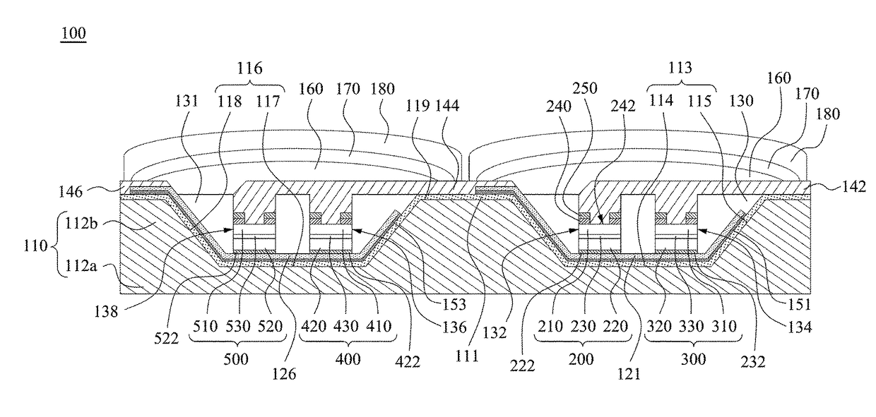
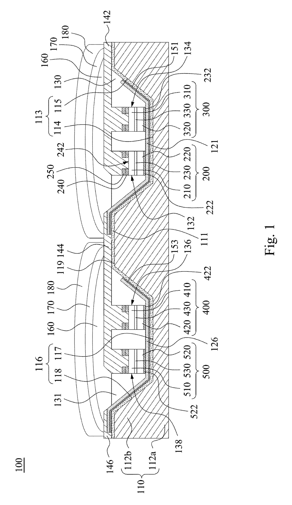
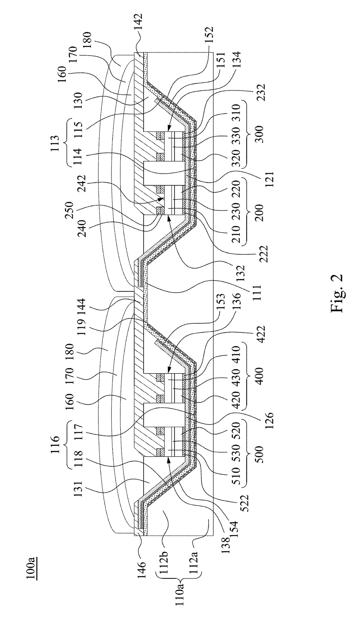
[0019]FIG. 1 is a schematic cross-sectional view of a light-emitting diode (LED) lighting device 100 according to some embodiments of the present disclosure. As shown in FIG. 1, the LED lighting device 100 includes a substrate 110, an isolation layer 111, bottom electrodes 121, 126, at least one vertical LED 200, at least one vertical LED 400, conductive bonding layers 222, 422, transparent sealing materials 130, 131, and a top electrode 144. The substrate 110 has a base portion 112a and a plurality of protruding portions 112b present on the base portion 112a. The base portion 1...


PUM


Abstract

A light-emitting diode (LED) lighting device includes a substrate, an isolation layer, a first bottom electrode, a second bottom electrode, at least one first vertical LED, a first conductive bonding layer, at least one second vertical LED, a second conductive bonding layer, a first transparent sealing material, a second transparent sealing material, and a top electrode. The substrate has a base portion and a plurality of protruding portions present on the base portion. The base portion and the protruding portions cooperate to define at least one first recess and at least one second recess. At least one of the first recess and the second recess has a bottom surface and at least one sidewall adjacent to the bottom surface. The bottom surface and the sidewall are reflective. The first vertical LED and the second vertical LED are electrically connected in series.

Description

BACKGROUND[0001]Technical Field[0002]The present disclosure relates to a light-emitting diode lighting device.[0003]Description of Related Art[0004]In recent years, light-emitting diode (LED) technologies have improved a lot, and LEDs with high power and high brightness have been presented to the market. In addition, the LEDs used as light bulbs have the advantage of long lifetime. Therefore, such LED light bulbs have the tendency to replace other conventional light sources. LEDs can be applied to various types of lamps, such as traffic lights, streetlights, and flashlights.[0005]Since LEDs gradually become mainstream light sources, improving properties of LEDs becomes an important issue, and this becomes the main goal in the R&D departments of the LED industries.SUMMARY[0006]According to an embodiment of the present disclosure, an LED lighting device includes a substrate, an isolation layer, a first bottom electrode, a second bottom electrode, at least one first vertical LED, a fir...

Claims


Application Information

Patent Timeline
IPC IPC(8): H01L33/60H01L33/44H01L33/38H01L33/08H01L33/54H01L33/50H01L33/56
CPCH01L33/60H01L33/44H01L33/38H01L33/08H01L33/54H01L33/502H01L33/56H01L25/0753H01L33/62H01L2224/18H01L2224/24137H01L2224/32245H01L2224/73267H01L2924/15153H01L2924/15156
Inventor CHEN, LI-YICHAN, CHIH-HUI
Owner MIKRO MESA TECH
Learn More