Electrical connector with electrical contacts protected by a layer of compressible material and method of making it

a compression material and electrical connector technology, applied in the direction of dielectric characteristics, electrical connection formation of printed elements, coupling device connections, etc., can solve the problems of adding to the thickness of the connector, not being as effective protected from damage, and damage to the electrical contacts

Inactive Publication Date: 2017-06-13
NEOCONIX INC
View PDF395 Cites 12 Cited by
  • Summary
  • Abstract
  • Description
  • Claims
  • Application Information

AI Technical Summary

Benefits of technology

[0014]The present invention is an electrical connector in which a layer of compressible material is positioned around (or adjacent to) the electrical contacts to protect the electrical contacts from damage or degradation and to assist in their functioning in an electronic device.
[0015]This layer of compressible material can provide significant protection in some cases from mechanical damage of the electrical contacts in some applications.
[0016]In some cases, it is beneficial to the functioning of this invention that the compressible material is taller in height than the electrical contacts (which may be spring contact elements emanating from a surface of the connector), so that the contacts are recessed below the surface of the compressible material in its uncompressed state. This configuration can prevent the lateral forces that may be most likely to impart damage to the connectors. It can also prevent or reduce the likelihood of upward or lifting forces on spring contacts such as cantilever beams, and can prevent or reduce the likelihood of the electrical contacts being marred or scratched or contaminated by other objects during fabrication, handling, packing, shipping, assembly, and use. The compressible nature of the material helps to absorb and dissipate energy from impacts, blows, vibrations, shocks, or other potentially deleterious forces that can damage the connector. It also allows the material to be compressed to a reduced thickness when compressive forces are applied to actuate the connector, such that the material doesn't interfere with the functioning of the spring contacts electrically and mechanically.
[0018]This layer of compressible material may also provide some resistance to moisture or fluid ingress in the region of the electrical interconnection between the electrical contacts on one member and the conductive electrical circuit elements on a mating member in some applications, when it is significantly compressed and when at least a portion of it fully surrounds the electrical contacts in the connector.
[0019]A layer of compressible material can also provide a mechanical “cushion” to absorb some of the impact forces and buffer the electrical contacts from damage from mechanical impacts to the electrical contacts, both during manufacturing and assembly and in the mating process or during repair or rework. This compressible material can also provide shock absorption in its compressed state, which helps dampen the impact of shock, drop, or vibration of the electronic device in which the connector is used, to reduce the possibility of a transient interruption to the electrical continuity through the connector and to reduce wear of the electrical contacts, as well as preventing other damage such as cracking of the housing or of soldered interconnections, in the case of surface mount soldered connectors.

Problems solved by technology

In such a connector system, the contact springs may at times be exposed to external forces which can cause damage, such as during handling, testing, inspection, and assembly into an electronic device.
However, because these housings are highly rigid, this type of protective structure adds to the thickness of the connector, which can be a detriment in miniaturized electronic systems such as mobile consumer products.
In some of the two piece stacked connectors, the contacts in the receptacle are recessed and hence somewhat protected, whereas the contacts in the header are not recessed and hence may not be as effectively protected from damage.
In a connector with surface emanating contacts or other non-recessed contacts, significant over-compression, upward displacement, or lateral displacement of the electrical contacts can cause damage to the electrical contacts.
Some electrical contacts are susceptible to damage such as scratching or contamination, or to plastic yielding due to excessive bending, twisting, lifting, over-compression or other rough handling.
In some cases, such damage reduces the effectiveness of the electrical contacts; in severe cases, the electrical contacts may become unusable or their performance compromised.
As connectors become more miniaturized to allow smaller electronic systems, the contact springs will likely be required to become smaller as well, and as such they may become more fragile.
Further, in some applications moisture or liquids may be present in the vicinity of the electrical connector, during functional use of the connector in the ultimate application.
Further, when an electronic device, such as a mobile phone, is powered on, and water or other conductive liquid penetrates to the electrical connections of a connector, a short circuit can occur which can interrupt the function of the device, and / or may cause permanent damage to critical components of the system.

Method used


Image

  • Electrical connector with electrical contacts protected by a layer of compressible material and method of making it
  • Electrical connector with electrical contacts protected by a layer of compressible material and method of making it
  • Electrical connector with electrical contacts protected by a layer of compressible material and method of making it

Examples


Embodiment Construction

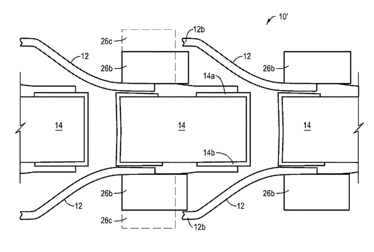
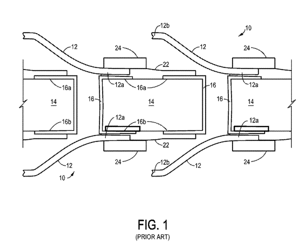
[0035]FIG. 1 shows, in a cross-sectional or cutaway view, an electrical connector (which may be an interposer, as in the example depicted in this view) 10 of the prior art with a plurality of electrical contacts 12 arranged in an array of electrical contacts (only part of which array is depicted in this view). The electrical connector 10 includes a non-conductive or insulating substrate 14 with conductive vias 16 extending therethrough from an upper surface 18 of the substrate 14 to a lower surface 20 of the substrate 14. (Of course, “upper” and “lower” surfaces refer to the orientation of the connector 10 as shown in the present illustration of FIG. 1; the electrical connector 10 and the electrical contacts 12 can generally be mounted in any orientation as desired, including vertical mountings, if the application requires it, and electrical contacts and electrical connectors originally mounted in one orientation might be moved to a different orientation, if desired.) One such elect...


PUM

PropertyMeasurementUnit
compressive modulusaaaaaaaaaa
thicknessaaaaaaaaaa

Abstract

Disclosed is an electrical connector having a substrate and movable electrical contacts which are mounted to the substrate and extend a distance D from the substrate. A layer of compressible material (such as a foam or elastomeric material) is positioned on the substrate adjacent at least some of the electrical contacts and ideally has an uncompressed thickness slightly greater than the distance D to provide for protection of the electrical contacts. When a mating electrical device such as an electrical connector or other circuit member is mated to the electrical connector with its electrical contacts and its layer of compressible material, the layer of compressible material is compressed to a thickness less than the distance D, allowing the contacts to make a suitable electrical interconnection to the mating electrical device. The compressible material may be selected which has a force-to-compression plot which includes at least one inflection, defining a first region on one side of the inflection where a given increment of force provides a larger increment of compression and a second region on the other side of the inflection where the same increment of compressive force provides a substantially smaller increment of compression. The compressible material can function to prevent damage to the movable electrical contacts from handling, packing, shipping, assembly, testing, connection and / or mating of the connector.

Description

CROSS REFERENCE TO RELATED PATENTS[0001]The present invention is related to the inventions described in the following United States Patents and Patent Applications:[0002]U.S. Pat. No. 7,371,073 entitled “Contact Grid Array”, issued May 13, 2008, to inventor John David Williams and assigned to Neoconix, Inc., the assignee of the present patent; this patent is sometimes referred to herein as the “Contact Array Patent”.[0003]U.S. Pat. No. 7,758,351 entitled “Method and System for Batch Forming of Spring Elements” issued Jul. 20, 2010, to inventors Dirk D. Brown et al. and also assigned to Neoconix, Inc. This patent is sometimes referred to herein as the “Batch Forming Patent”.[0004]U.S. patent application Ser. No. 13 / 310,647 entitled “Electrical Connector and Method of Making It”, filed Dec. 2, 2011 by David Noel Light and assigned to the assignee of the present invention. This patent is sometimes referred to herein as the “Filled Vias Patent”.[0005]The teachings of each of the foregoi...

Claims


Application Information

Patent Timeline
Patent Type & Authority Patents(United States)
IPC IPC(8): H01R43/16H01R12/70H01R12/73H01R12/71H01R13/24H05K3/28H05K3/40
CPCH01R43/16H01R12/7082H01R12/73H01R13/2442H05K3/285H01R12/714H01R13/2407H05K3/281H05K3/4015H05K2201/015H05K2201/0116H05K2201/0133H05K2201/0145H05K2201/0162H05K2201/10189H05K2201/10265H05K2201/2036Y10T29/49208
Inventor LIGHT, DAVID NOELWANG, HUNG-MINGBAKER, DAVID RODNEYNGUYEN, PETER THOPAO, DEXTER SHIH-WEI
Owner NEOCONIX INC
Why Eureka
Try Eureka