Sliding-type apparatus for thermotherapeutic treatment
a technology of thermotherapy and sliding type, which is applied in the field of sliding type apparatus for thermotherapy treatment, can solve the problem of taking up a lot of space even when not used, and achieve the effect of enhancing space occupancy and being easy to unfold
- Summary
- Abstract
- Description
- Claims
- Application Information
AI Technical Summary
Benefits of technology
Problems solved by technology
Method used
Image
Examples
first embodiment
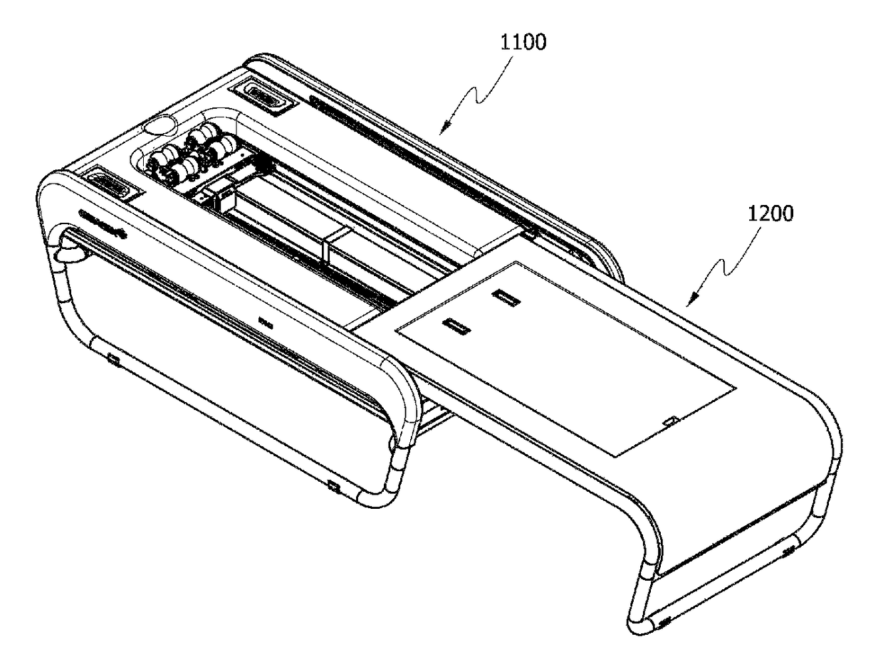
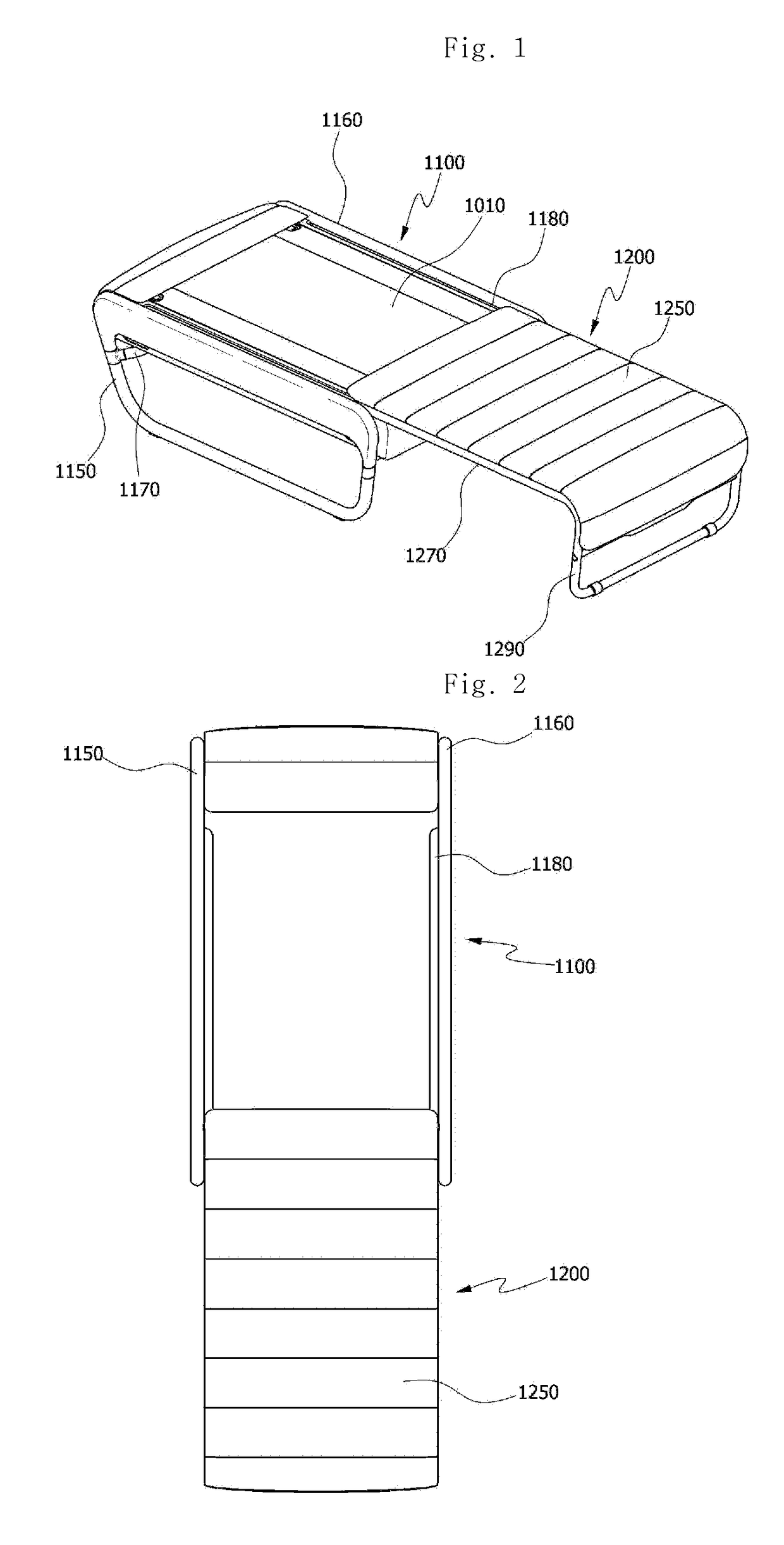
[0049]FIG. 1 is a perspective view illustrating a state in which an apparatus for thermo-therapeutic treatment is unfolded according to the present invention, and FIG. 2 is a schematic view schematically illustrating only a sliding structure in the apparatus for thermo-therapeutic treatment of FIG. 1.
[0050]As illustrated in FIG. 1, an apparatus for thermo-therapeutic treatment according to an embodiment of the present invention includes a body 1100 in which a thermo-therapeutic treatment device 1010 is disposed; and a lower bed member 1200 which is slid on the body 1100 to be unfolded or overlapped.
[0051]The body 110 includes the thermo-therapeutic treatment device 1010 and frames 1150 and 1160 which support the thermo-therapeutic treatment device 1010. Further, a guide groove 1180 is formed in a length direction between the thermo-therapeutic treatment device and the frame.
[0052]The thermo-therapeutic treatment device includes a thermo-therapeutic treatment mat having a hollow port...
first modified embodiment
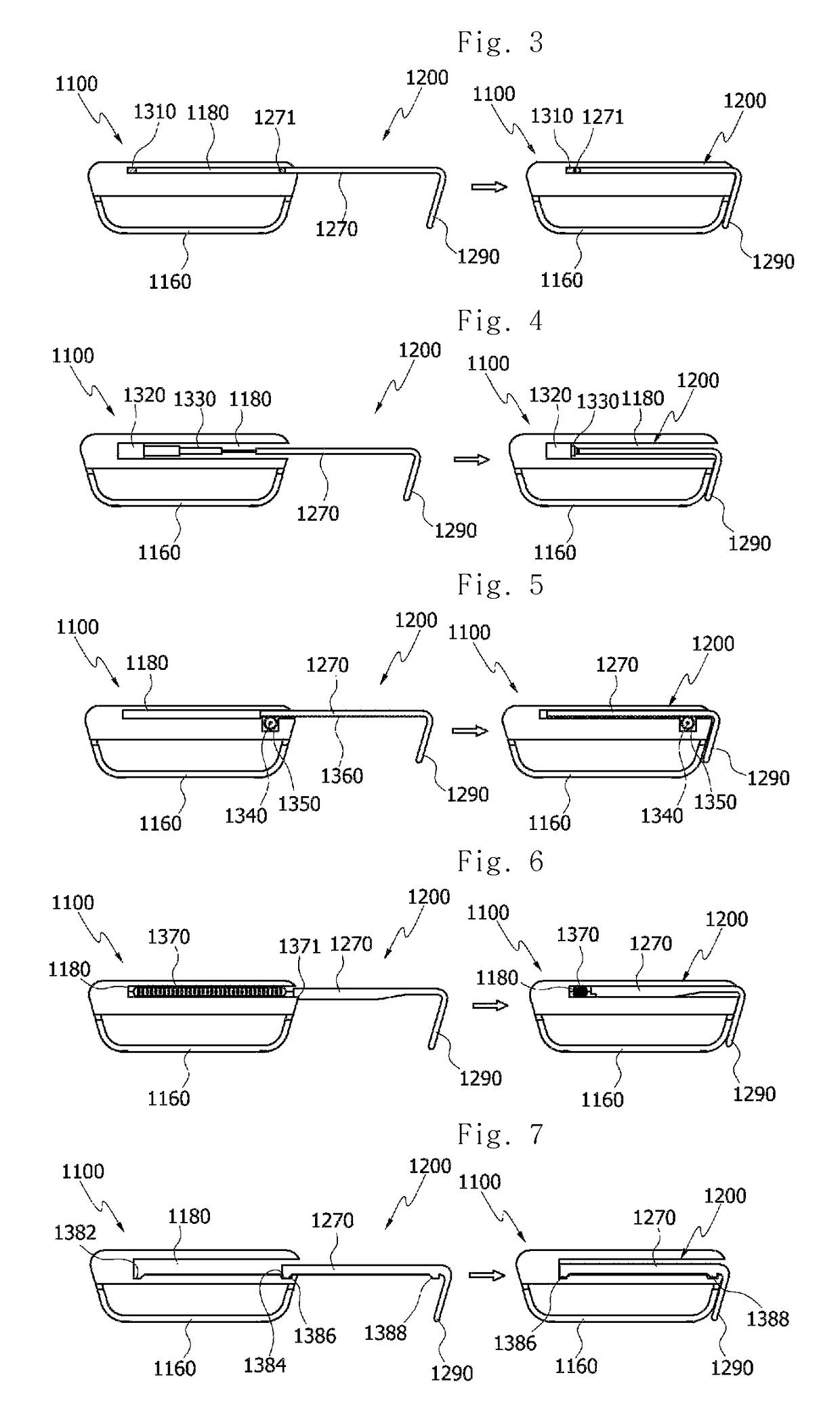
[0073]An automatic sliding structure uses an electromagnet, and FIG. 3 is a front view of the automatic sliding structure using the electromagnet. The electromagnet 1310 is installed at one side of the guide groove 1180 of the body 1100 so that the rod frame 1270 of the lower bed member 1200 is attracted by the electromagnet 1310 when electric power is supplied to the electromagnet 1310.
[0074]In this case, an iron-containing material which is easily attracted by a magnet is preferably applied to a distal end 1271 of the rod frame 1270 so that the electromagnet 1310 can function effectively. Of course, a magnet or another electromagnet which has opposite polarity to that of the electromagnet 1310 may be disposed at the distal end of the rod frame.
second modified embodiment
[0075]Another automatic sliding structure uses a cylinder structure, and FIG. 4 is a front view of the automatic sliding structure in which the cylinder structure is applied. A cylinder 1320 and a piston 1330 are provided at one side of the guide groove 1180 of the body 1100 so that the piston 1330 expands from and contracts into the cylinder 1320 in order to push and pull the distal end 1271 of the rod frame 1270.
[0076]At this time, the piston 1330 is in the form of multiple cylinders which gradually become smaller. A central one of the multiple cylinders has a rod shape, and a distal end of the rod is connected to the distal end 1271 of the rod frame 1270. That is, the distal end 1271 of the rod frame 1270 may be connected with the smallest cylinder, i.e., an endmost cylinder. Therefore, when the cylinder is used, the guide groove may have a length which is longer by a length of the piston portion. Further, this modified embodiment is not limited to this, and the piston 1330 may ...
PUM
 Abstract
Description
Claims
Application Information
 - R&D
- Intellectual Property
- Life Sciences
- Materials
- Tech Scout
- Unparalleled Data Quality
- Higher Quality Content
- 60% Fewer Hallucinations
Browse by: Latest US Patents, China's latest patents, Technical Efficacy Thesaurus, Application Domain, Technology Topic, Popular Technical Reports.
© 2025 PatSnap. All rights reserved.Legal|Privacy policy|Modern Slavery Act Transparency Statement|Sitemap|About US| Contact US: help@patsnap.com


