Suspension system for the front wheel of single-track two-wheeled vehicles namely motorcycles and bicycles

a two-wheeled vehicle and suspension system technology, applied in the direction of axle suspension, steering device, cycle equipment, etc., can solve the problems of frame pitch, displacing wheel and lower section of forks are of considerable mass, and suffer from certain disadvantages

Inactive Publication Date: 2017-06-27
FORMCEPT TECH & SOLUTIONS PVT
View PDF26 Cites 3 Cited by
  • Summary
  • Abstract
  • Description
  • Claims
  • Application Information

AI Technical Summary

Benefits of technology

[0005]In this regard it is a more specific objective of the present invention to provide in a single-track two-wheeled vehicle a linkage front suspension of only three main structural moving components with a manual method of steering control and a method of springing / dampening. It is another objective of this invention to provide in a vehicle a front suspension system that minimises diving during front wheel braking. It is another objective of the present invention to provide in a bicycle / motorcycle a suspension system which will minimise pitching motion at the handlebars, or other methods used for steering control. It is another objective of the present invention to provide in a vehicle a front suspension system that can utilise a lighter design of body / frame structure. A final objective of this invention is to provide in a two-wheeled vehicle superior road-holding for the different dynamic conditions encountered.

Problems solved by technology

This simple structure is an effective front suspension design but nevertheless suffers from certain disadvantages which have long been recognised but never completely overcome.
The main disadvantages associated with this design are, shock loads from the road surface onto the front suspension are directed towards the frame in the vicinity of the steering head area, which is far removed from the centre of gravity of the vehicle, where frame construction is relatively light but the displacing wheel and lower sections of the forks are of considerable mass.
This results in shock loads only being partially absorbed and transmits considerable load from the suspension in the direction of the frame, which invariably causes the frame to pitch.
There is also a tendency for the vehicle to ‘dive’, or pitch forwards and downwards, during hard braking of the front wheel due to the telescopic forks being raked out where displacement of the front wheel is both upwards and rearwards.
Further, with telescopic forks the load path of the shock loads to the frame is convoluted, where the steering head area and associated components have to be substantially stronger and heavier than need be if it were only to accommodate the torque necessary to effect steering.

Method used


Image

  • Suspension system for the front wheel of single-track two-wheeled vehicles namely motorcycles and bicycles
  • Suspension system for the front wheel of single-track two-wheeled vehicles namely motorcycles and bicycles
  • Suspension system for the front wheel of single-track two-wheeled vehicles namely motorcycles and bicycles

Examples


Embodiment Construction

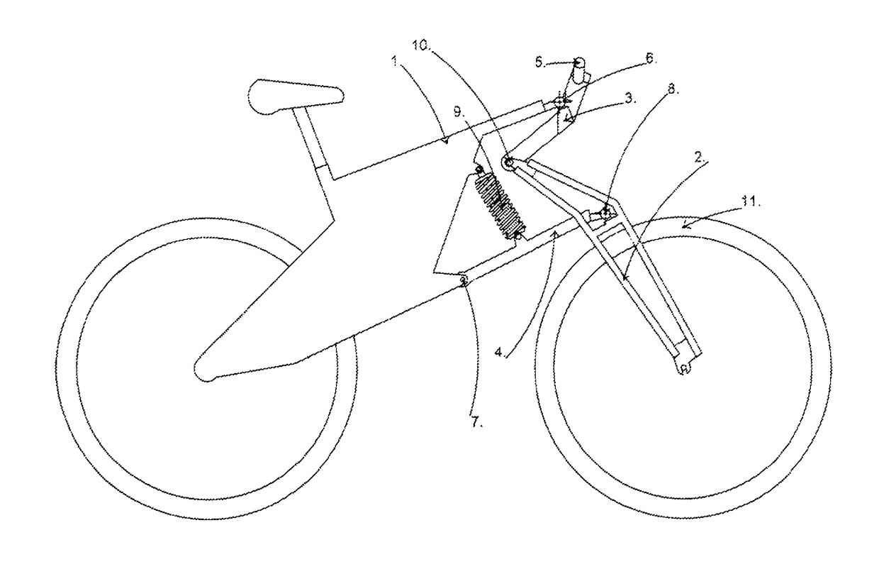
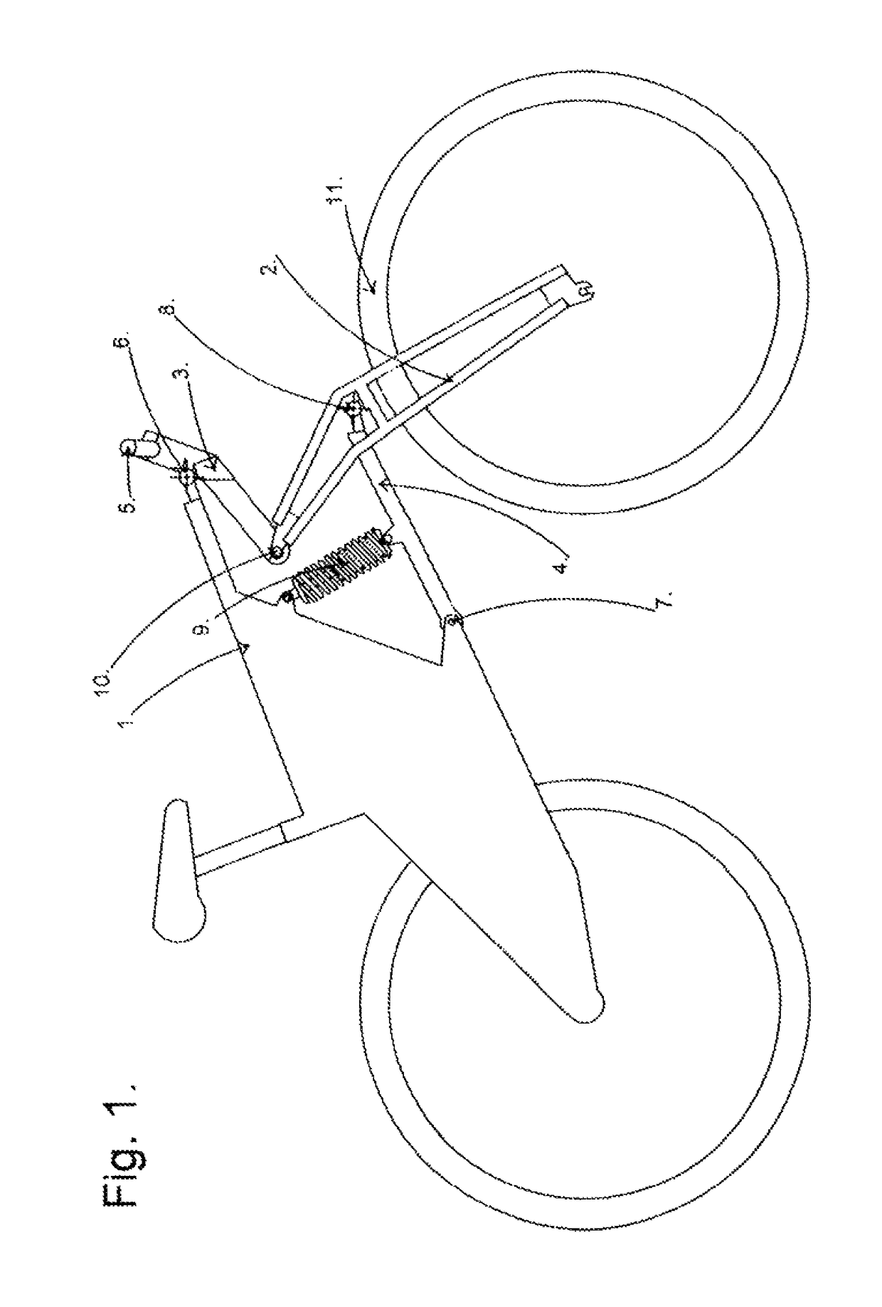
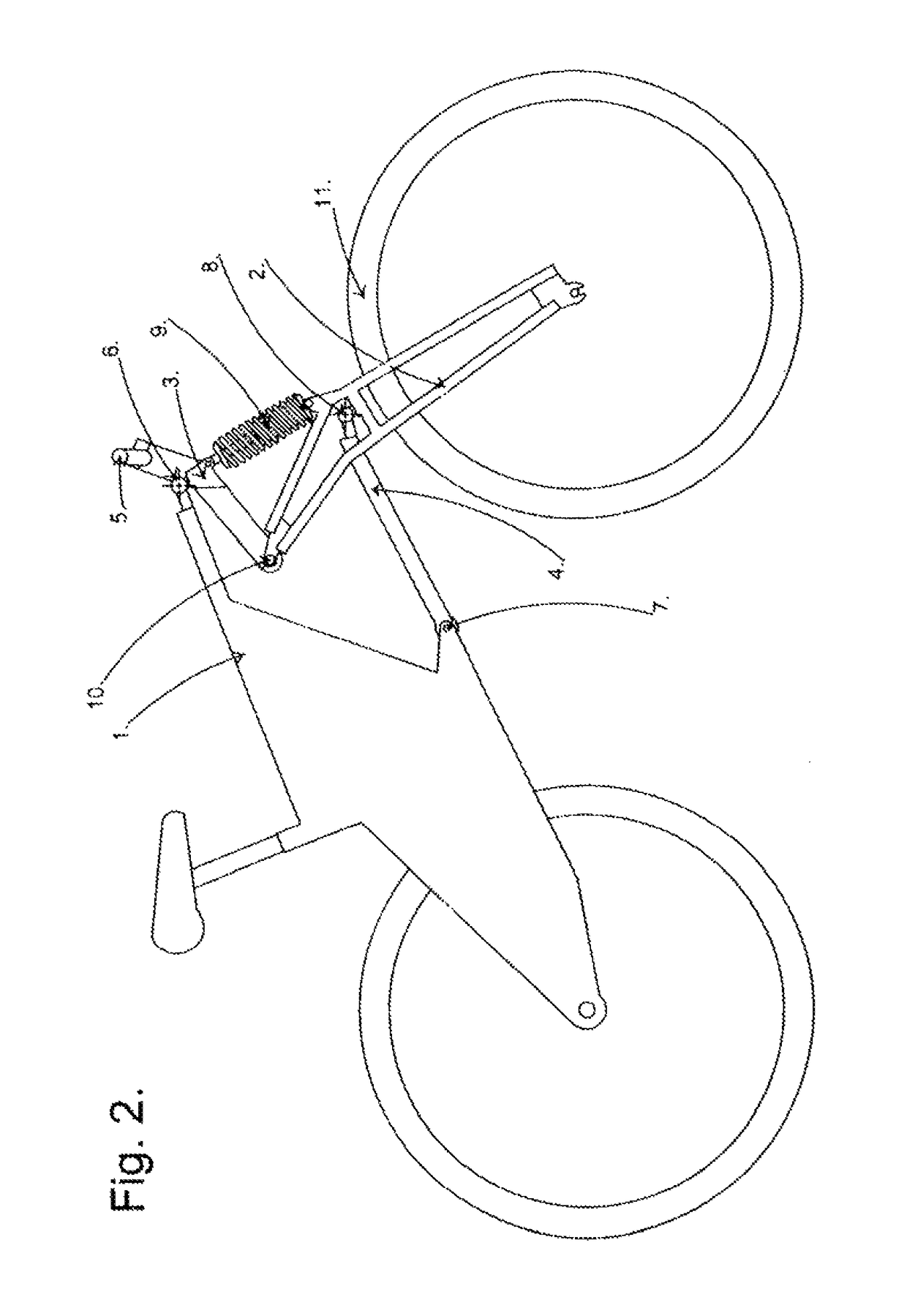
[0010]The suspension system includes a control arm (4) hinged with the body / frame structure (1) of the vehicle, extending forward from a pivot point (7) on the said frame structure along the longitudinal plane of which, for substantially vertical swinging motion at its outward end. The hinged pivot point (7) with the frame structure will have an axis of rotation extending transversely in respect to the longitudinal plane of the control atm (4). Attached at the outward end of said control arm (4) is a ball joint (8), or similar, permitting universal movement, where said ball joint (8), or similar, further attaches to a fork member (2).

[0011]The said lower ball joint (8), or similar, lies in the central longitudinal plane of the vehicle, which also corresponds with the centre plane of the front wheel (11) when it is in its unturned position. Said front wheel (11) is positioned below said lower ball joint (8) or similar means of universal movement.

[0012]The fork member (2) is connected...


PUM


Abstract

A linkage front wheel suspension system for two-wheeled vehicles comprising of a control arm hinged with the body of the vehicle, fork member, and steering member. An upper ball joint connects said steering member to the body of the vehicle and a lower ball joint connects the outer end of said control arm with said fork member. Fork member extends upwards and rearwards from said lower ball joint to hinge with said steering member. Steering member extends upwards and forwards from this pivot point to said upper ball joint. A method of steering control connects with said steering member. Means of springing / dampening connects with at least one of the said steering / suspension members. Said suspension system can utilize a lighter design of main frame, provide superior road-holding and can have reduced compression when front wheel braking.

Description

FIELD OF THE INVENTION[0001]The invention disclosed herein is generally related to motorcycles and bicycles. More particular, the present invention is related to suspension and steering systems for the front wheel of single-track two-wheeled vehicles.BACKGROUND[0002]Modern motorcycles and bicycles with front suspension systems are equipped universally with a fork type system. Such a system includes a pair of telescopic tubes that are inverted one inside the other and contain internal springs or springs and dampeners. The fork tubes are connected through a head assembly to a freely rotating steering column that is attached to the main frame of the vehicle. An axle for the front wheel is fixed perpendicular to the lower ends of said fork tubes. This simple structure is an effective front suspension design but nevertheless suffers from certain disadvantages which have long been recognised but never completely overcome. The main disadvantages associated with this design are, shock loads...

Claims


Application Information

Patent Timeline
Patent Type & Authority Patents(United States)
IPC IPC(8): B62K25/04B62K25/16B62K21/18B62K21/20
CPCB62K25/04B62K21/18B62K21/20B62K25/16B62K25/24
Inventor RAE, ROBERT
Owner FORMCEPT TECH & SOLUTIONS PVT
Why Eureka
Try Eureka