
Methods for enhancing propped fracture conductivity

a propped fracture and conductivity technology, applied in the direction of fluid removal, chemistry apparatus and processes, borehole/well accessories, etc., can solve the problems of increasing complexity and cost, reducing the and increasing the overall conductivity of propped fractures. , to achieve the effect of increasing or maintaining fracture conductivity, and increasing the overall conductivity of generated fractures

Active Publication Date: 2017-06-27
HALLIBURTON ENERGY SERVICES INC
View PDF46 Cites 5 Cited by
  • Summary
  • Abstract
  • Description
  • Claims
  • Application Information

AI Technical Summary

Benefits of technology

The method effectively prop open a greater proportion of fractures, maintaining higher conductivity and reducing costs by avoiding separate steps and using normal-density proppants, while preventing damage to fracture networks.

Problems solved by technology

However, proppant particulates tend to settle quickly to the lower side of the fracture, causing most of the created fractures on top of the proppant bed to close which greatly diminishes the conductive flow path.
Crosslinking of gel carrier fluid or use of lower density proppant can help to mitigate the settling, but these techniques can be complex and unreliable.
For example, use of crosslinked gels can increase complexity and cost, it can be difficult to evenly penetrate microfractures using gels, and high-viscosity fluids can cause permanent damage to fracture conductivity.
In another example, use of a lower density proppant having the proper density range can be time-consuming and can raise costs, and it can be difficult to select a lower density proppant such that the proppant neither moves to the top of the carrier fluid nor sinks to the bottom.

Method used


Image

  • Methods for enhancing propped fracture conductivity
  • Methods for enhancing propped fracture conductivity
  • Methods for enhancing propped fracture conductivity

Examples


example 1

Particle Size Distribution (PSD)

[0112]Table 2 provides PSD analysis for various samples of propping particulates used in this study.

[0113]

TABLE 2PSD ANALYSIS OF FINE PARTICULATESFine Particulated10 d50 d90 Material(μm)(μm)(μm)325-mesh silica flour 2.6417.143.4Ceramic microspheres9.4329.7110100-mesh sand111177263

example 2

Split Aluminum Cylinder

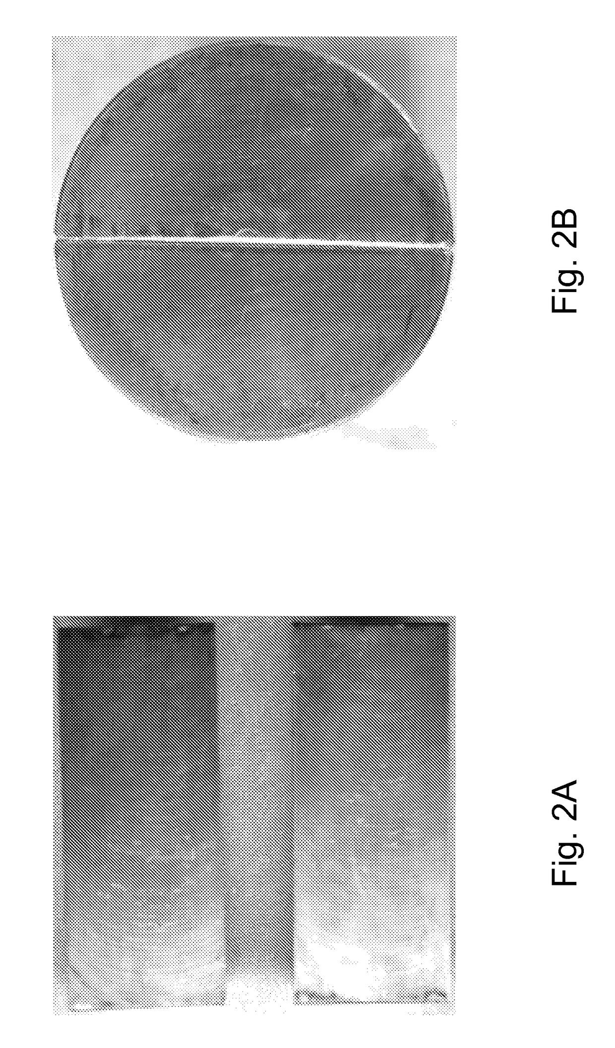
[0114]For control baseline testing, an aluminum cylinder with a 1-in. diameter and 2-in. length was cut along its axis into two halves using a saw. These two halves were machined to obtain smooth surfaces, and their axial edges were completely matched with one another to minimize any grooves formed on the side of the cylinder (FIGS. 2a-b).

example 3

Initial Permeability of Split Aluminum Cylinder (without Treatment)

[0115]To determine initial permeability of the split aluminum cylinder, the two halves of the cylinder were carefully matched and put back together before being installed in the Hassler sleeve. The confining pressure on the cylinder was gradually increased to 1,200 psi and backpressure was set to 200 psi. Effective permeability measurements (Ki values, Table 3) were determined with nitrogen gas using three different flow rates and their corresponding differential pressures, starting from the high flow rate (only lowest values shown here).

[0116]The “fracture conductivity” is generally the measurable unit for packed fractures when the crack width is not (or cannot be) measured. However, in many of the tests shown here, it is probable that the crack width is zero, at least for some (to nearly all) of the crack length, making “conductivity” an invalid representation for many of these measurements. For this reason, all da...


PUM

PropertyMeasurementUnit
viscosityaaaaaaaaaa
viscosityaaaaaaaaaa
temperatureaaaaaaaaaa

Abstract

Various embodiments disclosed relate to methods of treating a subterranean formations that provide enhanced fracture conductivity over other methods. In various embodiments, the present invention provides a method of treating a subterranean formation. The method can include obtaining or providing a composition including a tackifier. The composition can have a viscosity less than about 20 cP. The method can include placing the composition in a subterranean formation downhole. The method can also include fracturing the subterranean formation with the composition.

Description

PRIORITY APPLICATION[0001]This application is a U.S. National Stage Filing under 35 U.S.C. 371 from International Application No. PCT / US2013 / 069428, filed on 11 Nov. 2013, the application is incorporated herein by reference in its entirety.BACKGROUND OF THE INVENTION[0002]To create microfractures as part of complex fracture network in subterranean formations, operators rely on the use of low viscosity fluid (e.g., slickwater) as the main fracturing fluid and small size proppant (e.g., 100-mesh) as the propping agent. However, proppant particulates tend to settle quickly to the lower side of the fracture, causing most of the created fractures on top of the proppant bed to close which greatly diminishes the conductive flow path. Crosslinking of gel carrier fluid or use of lower density proppant can help to mitigate the settling, but these techniques can be complex and unreliable. For example, use of crosslinked gels can increase complexity and cost, it can be difficult to evenly penet...

Claims


Application Information

Patent Timeline
Patent Type & Authority Patents(United States)
IPC IPC(8): C09K8/46C09K8/467E21B43/267C09K8/88C09K8/565C09K8/80E21B43/26C09K8/64C09K8/68C09K8/575C09K8/035C09K8/60C09K8/74C09K8/52
CPCC09K8/68C09K8/467C09K8/565C09K8/5751C09K8/64C09K8/685C09K8/80C09K8/805C09K8/88E21B43/26E21B43/267C09K8/035C09K8/52C09K8/602C09K8/74C09K2208/02C09K2208/12
Inventor NGUYEN, PHILIP D.MOCK, BRIAN D
Owner HALLIBURTON ENERGY SERVICES INC
Learn More