Recognition object detecting apparatus

a recognition object and detecting apparatus technology, applied in the field of recognition object detecting apparatus, can solve the problems of increased processing load, reduced accuracy, and increased cost of manufacturing the apparatus, so as to increase the accuracy of detecting recognition objects and suppress processing load

Active Publication Date: 2017-06-27
DENSO CORP
View PDF64 Cites 14 Cited by
  • Summary
  • Abstract
  • Description
  • Claims
  • Application Information

AI Technical Summary

Benefits of technology

[0009]An embodiment provides a recognition object detecting apparatus which increases accuracy in detecting a recognition object while suppressing processing load.

Problems solved by technology

However, as the sensitivity increases, the image of the tail lights or the headlights existing at a short distance (high luminance) is easily saturated in the image taken by the in-vehicle camera.
However, when performing imaging multiple times with changing imaging sensitivity as the conventional technique described above, the processing load substantially increases.
The increased processing load causes a problem that the cost of manufacturing the apparatus increases and a problem that the miniaturization of the apparatus is prevented as the amount of heat generation increases.
Note that such problems can be caused not only in the technique in which tail lights of a leading vehicle or headlights of an oncoming vehicle are detected as a recognition object but in a technique in which other recognition objects are detected.

Method used


Image

  • Recognition object detecting apparatus
  • Recognition object detecting apparatus
  • Recognition object detecting apparatus

Examples


first embodiment

[0035][First Embodiment]

[0036](1. General Configuration)

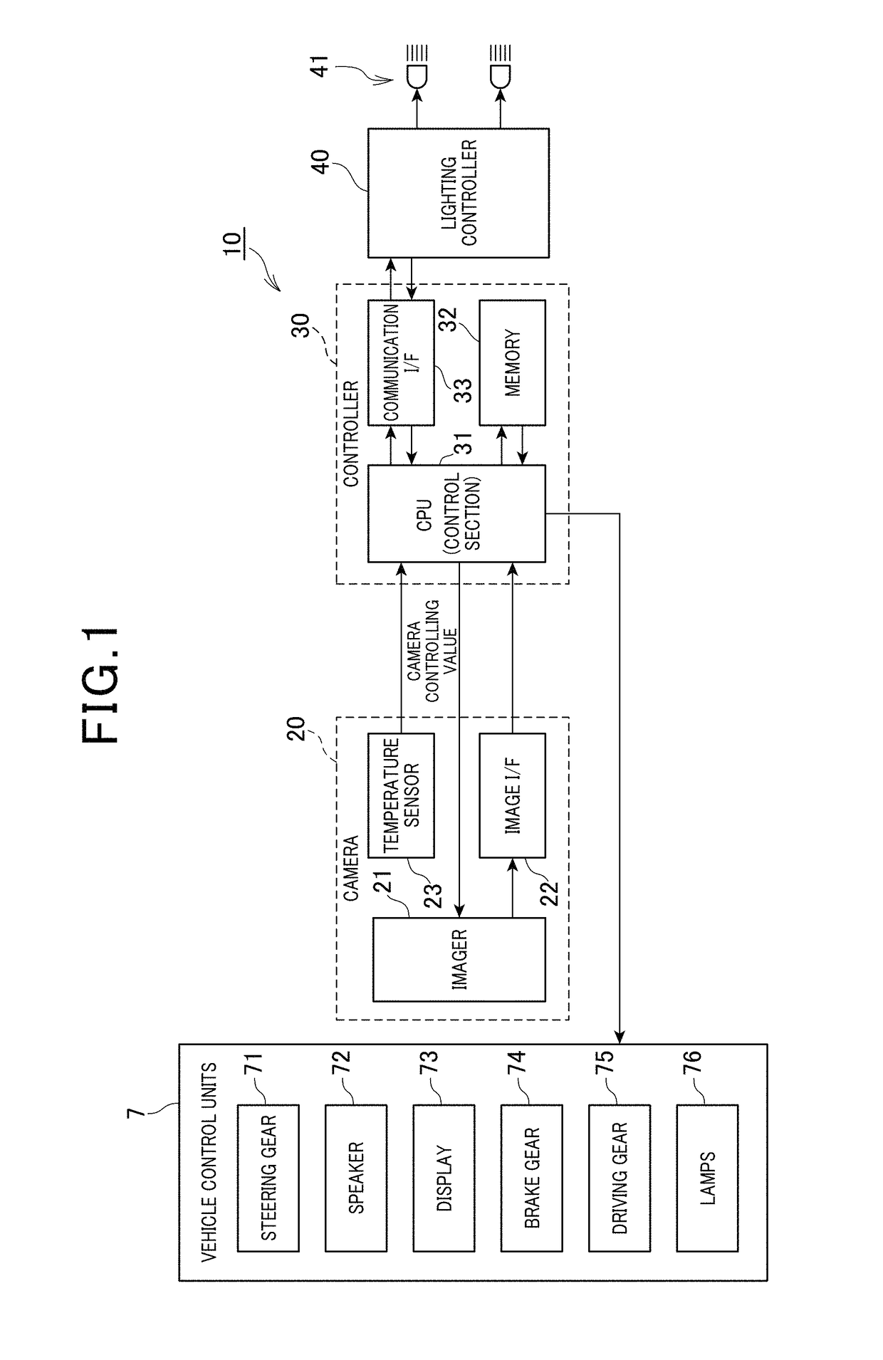
[0037]FIG. 1 is a block diagram showing a configuration of a vehicle control system 10 of the embodiment.

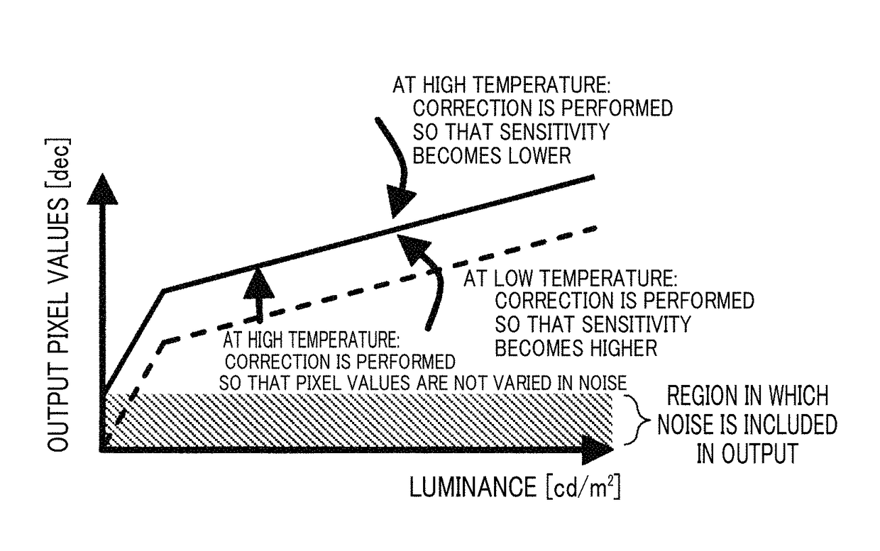
[0038]The vehicle control system 10 is installed in a predetermined vehicle. The vehicle control system 10 performs auto high beam control under which the lighting state of headlights 41 of the own vehicle is changed, depending on whether or not another vehicle (leading vehicle or oncoming vehicle) is travelling ahead of the predetermined vehicle (own vehicle). While performing the auto high beam control, the lighting state of headlights 41 is automatically set to low beam if a leading vehicle or an oncoming vehicle is present and to high beam if neither a leading vehicle nor an oncoming vehicle is present.

[0039]To realize the auto high beam control described above, the headlight control system 10 includes an in-vehicle camera 20 (hereinafter, simply referred to as “camera”) which takes an image of a scene ahead of the own v...

second embodiment

[0090][Second Embodiment]

[0091]

[0092]FIG. 10 is a block diagram illustrating a general configuration of a vehicle control system 1 according to a second embodiment. The vehicle control system 1 detects various objects that are present around the vehicle. Based on the detection results and various pieces of information acquired from in-vehicle sensors 5, the vehicle control system 1 performs various vehicle controls using vehicle control units 7.

[0093]The in-vehicle sensors 5 include sensors that detect the behaviors of the vehicle, and sensors that detect the environmental features surrounding the vehicle. The sensors that detect the behaviors of the vehicle include, for example, a vehicle speed sensor, various acceleration sensors and a steering-angle sensor. The sensors that detect the environmental features surrounding the vehicle include, for example, a unit for outputting position data of the own vehicle (e.g., GPS (global positioning system)), a unit serving as a source of sup...

third embodiment

[0126][Third Embodiment]

[0127]Referring now to FIG. 16, a third embodiment is described. The third embodiment has a basic configuration similar to that of the second embodiment, with an only difference from the second embodiment being the object detection process performed by the signal processing section 120. Therefore, the following description is focused on the difference, omitting the explanation on the common configuration. Further, in the second and the subsequent embodiments, the components identical with or similar to those in the second embodiment are given the same reference numerals for the sake of omitting unnecessary explanation.

[0128]

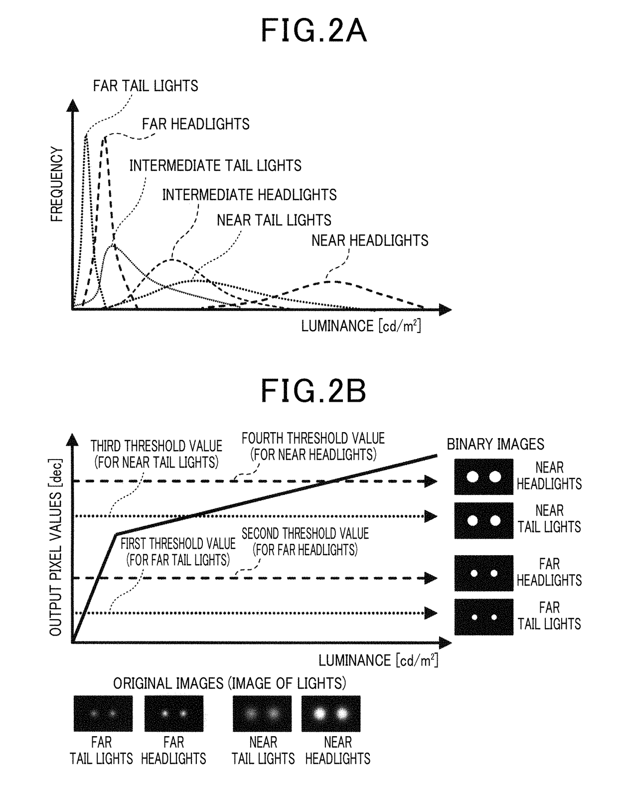
[0129]FIG. 16 is a flow diagram illustrating an object detection process according to the third embodiment. Upon start of the present process, the signal processing section 120 performs scene estimation (step S110) and determines whether or not the estimated scene is a specific scene (step S120).

[0130]If it is determined that the estimated...


PUM


Abstract

A recognition object detecting apparatus is provided which includes an imaging unit which generates image data representing a taken image, and a detection unit which detects a recognition object from the image represented by the image data. The imaging unit has a characteristic in which a relation between luminance and output pixel values varies depending on a luminance range. The detection unit binarizes the output pixel values of the image represented by the image data by using a plurality of threshold values to generate a plurality of binary images, and detects the recognition object based on the plurality of binary images.

Description

CROSS-REFERENCE TO RELATED APPLICATION[0001]This application is a continuation-in-part of U.S. Ser. No. 13 / 486,366 field Jun. 1, 2012 and claims priority from earlier Japanese Patent Application No. 2011-126474 filed Jun. 6, 2011, the description of which is incorporated herein by reference.BACKGROUND[0002]Technical Field[0003]The present invention relates to a recognition object detecting apparatus which detects a recognition object from an image taken by an in-vehicle camera.[0004]Related Art[0005]Conventionally, a technique is known which detects a predetermined recognition object from an image taken by an in-vehicle camera. For example, JP-A-2009-61812 discloses a technique in which an image of a scene ahead of a vehicle traveling at night is taken by using an in-vehicle camera. Next, tail lights of a leading vehicle or headlights of an oncoming vehicle are detected from the taken image as a recognition object. By using this technique, the control is realized under which headlig...

Claims


Application Information

Patent Timeline
Patent Type & Authority Patents(United States)
IPC IPC(8): G06K9/00G06K9/38G06V10/28
CPCG06K9/00825G06K9/38G06V20/584G06V10/28
Inventor MURAO, TOSHIKAZUKIMURA, TAKAYUKISHIOTA, KENTAROUSHIRAI, NORIAKISUGIYAMA, NAOKI
Owner DENSO CORP
Why Eureka
Try Eureka