Vibration electricity generation device
a technology of vibration electricity and generation device, which is applied in the direction of dynamo-electric components, dynamo-electric machines, electrical apparatus, etc., can solve the problems of deteriorating generating efficiency, achieve the effect of improving the electricity generation efficiency of vibration electricity generation device, keeping the coefficient of kinetic friction low, and improving the efficiency of vibration electricity generation
- Summary
- Abstract
- Description
- Claims
- Application Information
AI Technical Summary
Benefits of technology
Problems solved by technology
Method used
Image
Examples
first modified embodiment
[0093]At first, a first modified embodiment will be described.
[0094]FIG. 7 is an exploded view of a movable unit 140 according to another embodiment of the present invention.
[0095]As illustrated in FIG. 7, the basic structure of the movable unit 140 is almost the same as that of the foregoing embodiment but the structure of weight members 148A and 148B which are arranged on both side ends of the yokes 44 is different from that of the foregoing embodiment.
[0096]In this embodiment, the weight members 148A and 148B are separately formed from the yokes 44. In detail, each of the weight members 148A and 148B is a soft iron block which has a horizontal cross-section of a vertically long rectangle. The weight members 148A and 148B are fixed on the yokes 44 by adhesion or welding.
[0097]The weight member 148A fixed on the yokes 44 also confines the lower end 50b of the coil spring 50 held by the holding portion 46f of the magnet supporting member 46 from below, thereby firmly maintaining the...
second modified embodiment
[0100]Next, a second modified embodiment will be described.
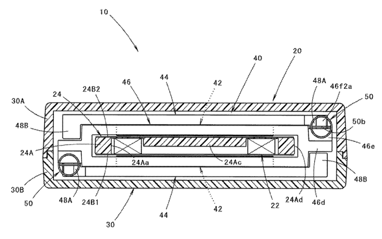
[0101]FIG. 8A is a sectional view of a coil supporting member 124 according to a modified embodiment of the present invention. FIG. 8A corresponds to an enlarged view showing the main portion of FIG. 3.
[0102]As illustrated in FIG. 8A, the basic structure of the coil supporting member 124 of this modified embodiment is almost the same as that of the foregoing embodiments but the pair of right and left side surfaces 24Ad of the supporting main body 24A are also given a friction reducing treatment.
[0103]Namely, in this modified embodiment, the right and left side surfaces 24Ad of the coil supporting member 124 constitute friction reduced surfaces 160 having a friction reducing treatment such as Teflon (registered trade mark) coating applied.
[0104]According to this modified embodiment, even if the up and down vibrating movable unit 40 is displaced in the direction perpendicular to the thickness direction of the coil supporting m...
third modified embodiment
[0105]Next, a third modified embodiment will be described.
[0106]FIG. 8B is a sectional view of a coil supporting member 224 according to a modified embodiment of the present invention. FIG. 8B corresponds to an enlarged view showing the main portion of FIG. 3.
[0107]As illustrated in FIG. 8B, the basic structure of the coil supporting member 224 of this modified embodiment is almost the same as that of the foregoing embodiments but the back surface of the supporting main body 24A is formed as a friction reduced surface 260 having a friction reducing treatment such as Teflon coating applied instead of the friction reducing film 24B2 being attached.
[0108]In this modified embodiment, the same effects and operations as the foregoing embodiment may be obtained.
PUM
 Abstract
Description
Claims
Application Information
 - R&D
- Intellectual Property
- Life Sciences
- Materials
- Tech Scout
- Unparalleled Data Quality
- Higher Quality Content
- 60% Fewer Hallucinations
Browse by: Latest US Patents, China's latest patents, Technical Efficacy Thesaurus, Application Domain, Technology Topic, Popular Technical Reports.
© 2025 PatSnap. All rights reserved.Legal|Privacy policy|Modern Slavery Act Transparency Statement|Sitemap|About US| Contact US: help@patsnap.com


