Amphibious pumping vehicle

a technology for amphibious vehicles and pumping machines, which is applied in the direction of machines/engines, steering initiations, vessel construction, etc., can solve the problems of limited ability to recirculate manure, and achieve the effect of improving the handling characteristics of the vehicl

Active Publication Date: 2017-07-04
NUHN INDS
View PDF12 Cites 8 Cited by
  • Summary
  • Abstract
  • Description
  • Claims
  • Application Information

AI Technical Summary

Benefits of technology

[0010]The fluid pump may comprise a pump housing configured for immersion within the fluid. The pump housing may comprise a bottom fluid inlet and at least two tangential fluid outlets. A greater number of tangential fluid outlets may be provided, for example three fluid outlets. The tangential fluid outlets may be combined into a single fluid conduit for directing the combined output of the fluid pump to a desired location. The vehicle may comprise structure configured to cause raising and lowering of the fluid pump, especially the fluid pump housing, relative to the vehicle body. For example, a hydraulically or electrically driven linear actuator may be provided on the vehicle and configured to raise and lower the fluid pump. This may be accomplished via a telescoping structure or a lever structure of the vehicle. The tangential fluid outlets may be equipped with flexible or telescoping connections to the single fluid conduit. Lowering the fluid pump for immersion into the fluid obviates the need for priming the fluid pump, which can be problematic when the fluid is manure comprising solid materials that can plug the pump or priming structure. Immersion of the pump also simplifies intermittent operation of the pump, due to eliminating potential loss of prime, and reduces the need for pump maintenance.
[0014]The location of at least the ground engaging propulsion structure, the power source and the fluid pump may be selected to provide a desired location for a center of gravity of the vehicle. The desired location for the center of gravity of the vehicle may be selected to improve handling characteristics of the vehicle while floating. The center of gravity may be located along the longitudinal centerline of the vehicle. The center of gravity may be located substantially in the middle of the vehicle, for example at an intersection of longitudinal centerline of the vehicle and the transverse centerline of the vehicle. The center of gravity may be located rearward of the transverse centerline of the vehicle. The center of gravity may be located forward of the transverse centerline of the vehicle. Thus the ground engaging propulsion structure, power source, and fluid pump cooperate together to improve handling characteristics of the vehicle.

Problems solved by technology

They are therefore limited in their ability to recirculate manure to the middle of large lagoons, which are becoming increasing common as the size of animal husbandry operations increases.

Method used


Image

  • Amphibious pumping vehicle
  • Amphibious pumping vehicle
  • Amphibious pumping vehicle

Examples


Embodiment Construction

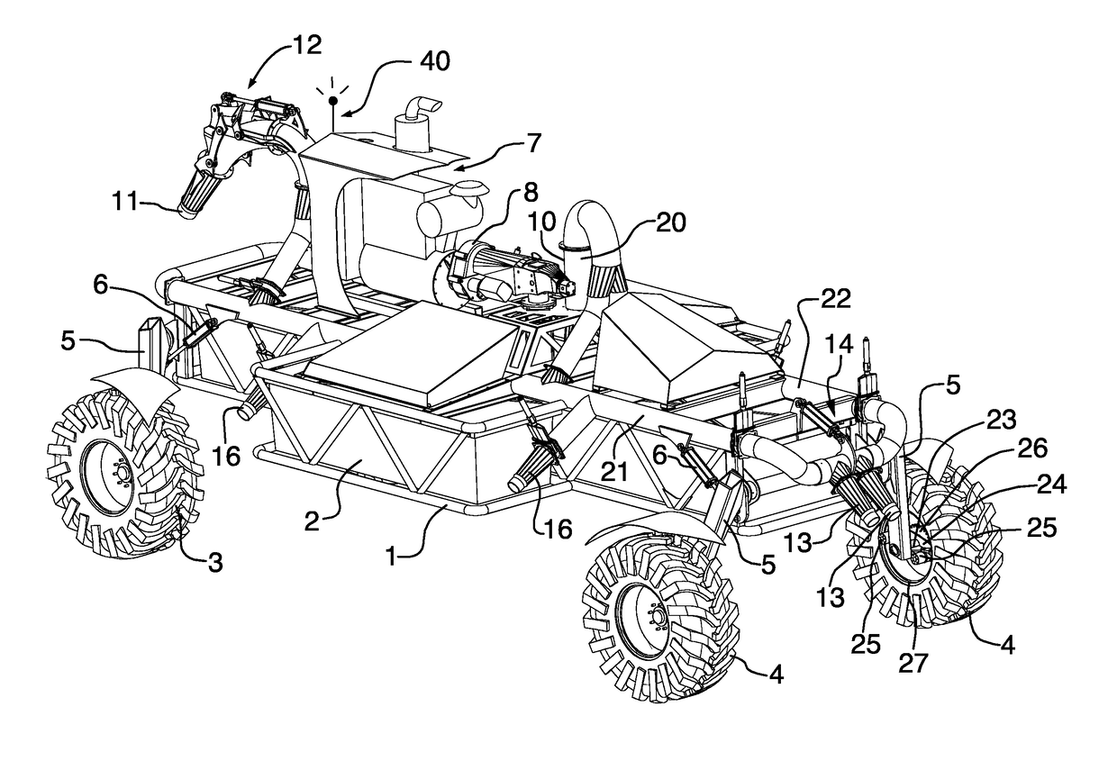
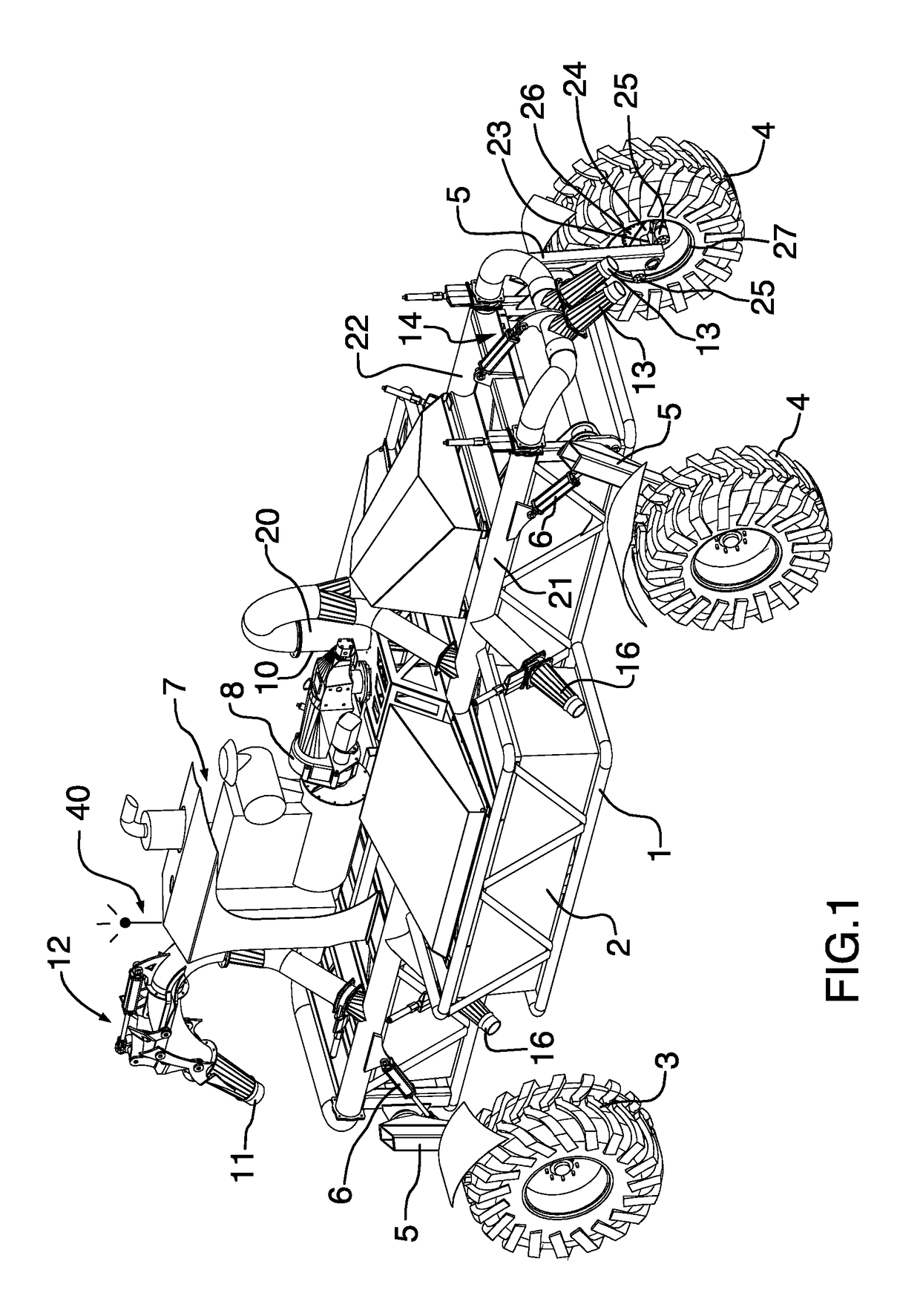
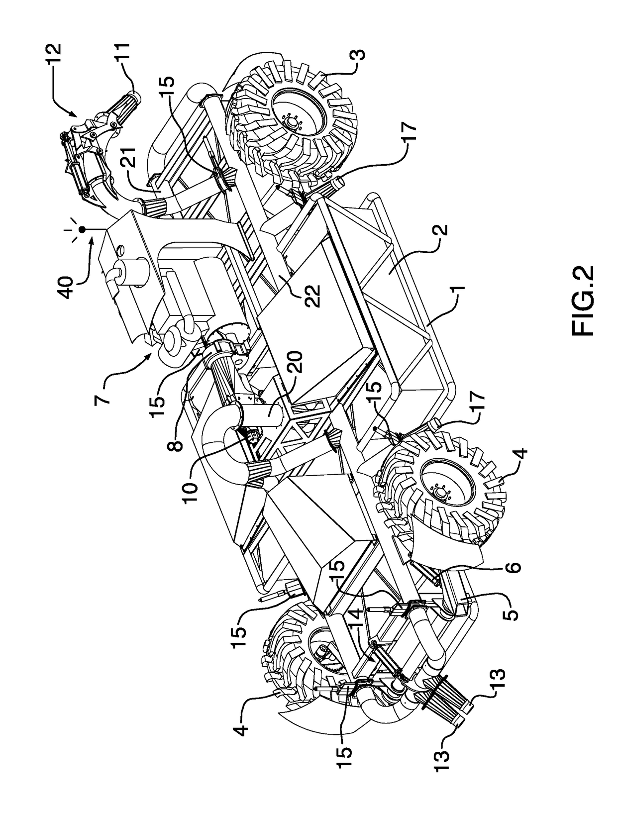
[0026]In describing the figures, like features are referred to by like reference numerals. Although not all features indicated on a particular drawing are necessarily described with reference to that drawing, all of the features are described with reference to at least one of the drawings.

[0027]Referring to FIGS. 1-3, an amphibious vehicle comprises a vehicle body 1 incorporating buoyant elements 2. The buoyant elements comprise flotation tanks of the type that may be foam filled and used, for example, in the construction of floating docks. The vehicle comprises a ground engaging propulsion structure comprising two sets of wheels 3, 4. Each wheel is rotatably mounted to lever structure 5 that is pivotally attached to the vehicle body. Each lever structure 5 is driven by a hydraulic actuator 6 that is operable to cause raising and lowering of the wheels 3, 4 by pivoting of the lever structure5. A power source 7 comprising an internal combustion engine, for example a diesel engine, is...


PUM


Abstract

An amphibious pumping vehicle comprising: a floatable vehicle body; ground engaging propulsion structure configured to raise and lower relative to the vehicle body; a fluid pump; a first fluid nozzle configured to direct fluid through the air, the fluid nozzle connected by a fluid conduit to the fluid pump; and, a power source configured to provide power to both the ground engaging propulsion structure and the fluid pump. The vehicle is particularly well suited to pumping and recirculating fluid within manure lagoons and is able to be driven up out of the lagoon when the lagoon level has been lowered.

Description

CROSS-REFERENCE TO RELATED APPLICATIONS[0001]This application is a continuation of international patent application PCT / CA2014 / 050789, filed Aug. 19, 2014, which claims the benefit of U.S. patent application 61 / 867,598 filed Aug. 18, 2013, the entire contents of which are herein incorporated by reference.TECHNICAL FIELD[0002]The invention relates to pumps and vehicles equipped for pumping. In particular, the invention relates to manure pumps and amphibious vehicles equipped for pumping liquid manure, such as animal manure contained in a farm lagoon.BACKGROUND[0003]Manure produced during animal husbandry, particularly hog and cattle manure, is transferred by washing to a pit or lagoon for storage prior to removal for land application or further processing. During storage, a crust can develop on the surface of the pit or lagoon that must be disrupted prior to or during removal of the manure. Pumps are employed for this purpose with jets that return a percentage of the manure back to t...

Claims


Application Information

Patent Timeline
Patent Type & Authority Patents(United States)
IPC IPC(8): B60F3/00A01C3/02A01C23/04
CPCB60F3/0007A01C3/026A01C23/045B60F3/0038B60F3/0061B60F3/003B60F2301/00B63H25/02B63H2025/028F04D13/02
Inventor NUHN, IAN
Owner NUHN INDS
Why Eureka
Try Eureka