Inclined plates for CSO

a technology of inclined plates and cso, which is applied in the direction of sedimentation settling tanks, sewage draining, separation processes, etc., can solve the problems affecting the construction cost of any site improvement, and achieve the effect of reducing cell length, increasing flow rate, and equal length to width ratio

Active Publication Date: 2017-07-04
FRESH CREEK TECH LLC
View PDF7 Cites 2 Cited by
  • Summary
  • Abstract
  • Description
  • Claims
  • Application Information

AI Technical Summary

Benefits of technology

[0015]When the flow into the chamber intensifies during a high level storm event, the water level will rise and crest the dry weather flow weir. This weir is strategically located at an elevation to encourage the first flush flow through the inclined lamellae or cells. By approximation of the cresting portion of the water flow, the device will preserve the surface loading necessary to remove sediment particle sizes to meet the water quality standard of a given EPA rule. This cresting portion is able to reach the elevation of the overflow weir and crest this second weir until the water elevation exceeds the ceiling elevation. Effectively the water column first flows through the net cavity to remove the floatables that exceed the predetermined net opening size. Then the water column is stratified in one to three layers depending on the flow intensity.
[0032]The ribbed cells also provide intermediate support to the cell floor and ceiling which permits larger spans across the ribs without sacrificing the functionality of the inclined cells. The length of the cell assembly that runs parallel to the in- and outflow axis permits a matching net length and net length provides proportional net flow through area which extends its replacement life-cycle.

Problems solved by technology

In the USA, surface water run-off quality is regulated by the Clean Water Act and affects the construction cost of any site improvement for which a “Storm water Permit” is required from the EPA.

Method used


Image

  • Inclined plates for CSO
  • Inclined plates for CSO
  • Inclined plates for CSO

Examples


Embodiment Construction

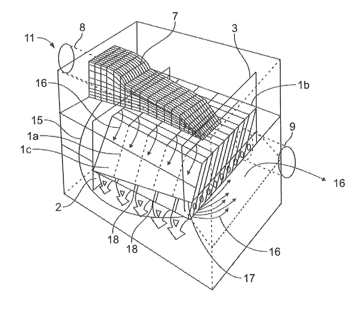
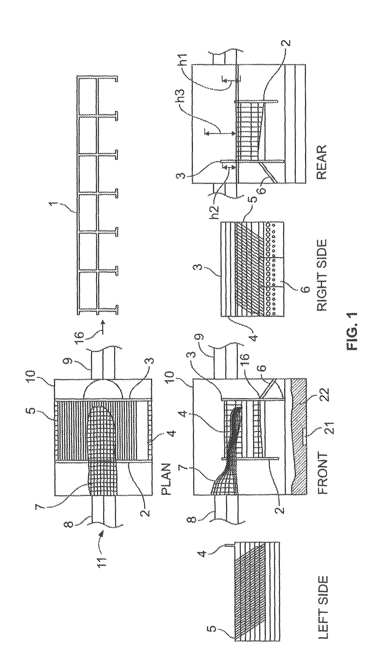
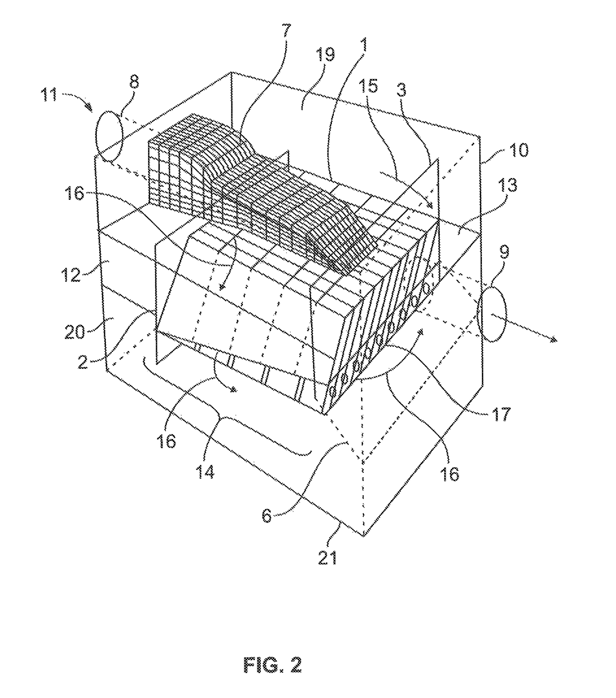
[0048]While this invention is susceptible of embodiments in many different shape and size, the present invention is shown and described in the attached drawings.

[0049]The purification goal of the inclined cells is to remove as much sediment by means of exposure of the flowing water to settling area provided by the cells. This creates a condition where the relative movement of the settling particle and the encapsulating water separate. The water and the particle move “En Masse” as a closed cell and only the density difference facilitates relocation of the particle within the cell. There must be equality of this condition throughout the inclined cell settling device to preserve the settling performance and repeatability of the performance. By maintaining a constant pressure head and placing orifices across the length of the hinged baffle and shaping matching the flow path length of all cells to its neighboring cells from the crest point of the dry-weather flow weir to the orifice, the...


PUM

PropertyMeasurementUnit
Reynolds numberaaaaaaaaaa
lengthaaaaaaaaaa

Abstract

This device serves to improve water quality under gravity flow conditions. The water quality treatment device traps floating debris with replaceable netting, it contains oil spills and settles sediment in self-cleaning settling cells above a collection bunker inside a chamber. The device directs the water below the inclined cells, through the inclined cells, or over the inclined cells, depending on the inflow intensity. All inflowing water enters the net cavity and the net is supported by the inclined cell assembly. The pollutant collection surfaces are overlapping each other and aligned with the water flow direction. A hinged baffle with orifices controls the flow rate through the inclined cells. The netting is replaceable when filled with debris through an access opening in the ceiling of the chamber. The sediment bunker is cleaned through access openings in the ceiling from the chamber inflow side and the exit side.

Description

CROSS-REFERENCES TO RELATED APPLICATION[0001]This application claims priority to U.S. Provisional Patent Application No. 61 / 718,083, filed on Oct. 24, 2012, entitled Inclined Plates For CSO, the entire contents of which is incorporated herein by this reference.FIELD OF INVENTION[0002]A water quality treatment device and in particular a device for cleaning storm water that traps debris in storm water with replaceable netting while containing oil spills and settling sediment in self-cleaning settling lamellae or cells above a collection bunker inside a chamber.BACKGROUND OF THE INVENTION[0003]U.S. Pat. No. 3,706,384 (384 patent) in claim 1 teaches the flow distribution through a plurality of inclined plates, lamellae or cells in parallel to each other by means of entering the water into the lowermost side of the plates, lamellae or cells and discharging the water at the uppermost portion of the inclined plates, lamellae or cells. The '384 patent teaches the extension of the lamellae o...

Claims


Application Information

Patent Timeline
Patent Type & Authority Patents(United States)
IPC IPC(8): E03F1/00B01D21/00E02B5/08E03F5/16
CPCE03F1/00B01D21/0045B01D21/0051E03F5/16B01D21/006B01D21/0039B01D21/0087E02B5/085
Inventor MORAN, DENNIS R.TRNKA, WALTER C.BRUIJN, HANS DE
Owner FRESH CREEK TECH LLC
Why Eureka
Try Eureka