Inclined plates for cso

a technology of inclined plates and cso, which is applied in the direction of sedimentation settling tanks, sewage draining, separation processes, etc., can solve the problems affecting the construction cost of any site improvement, and achieve the effect of reducing cell length, increasing flow rate, and equal length to width ratio

Active Publication Date: 2014-04-24
FRESH CREEK TECH LLC
View PDF4 Cites 4 Cited by
  • Summary
  • Abstract
  • Description
  • Claims
  • Application Information

AI Technical Summary

Benefits of technology

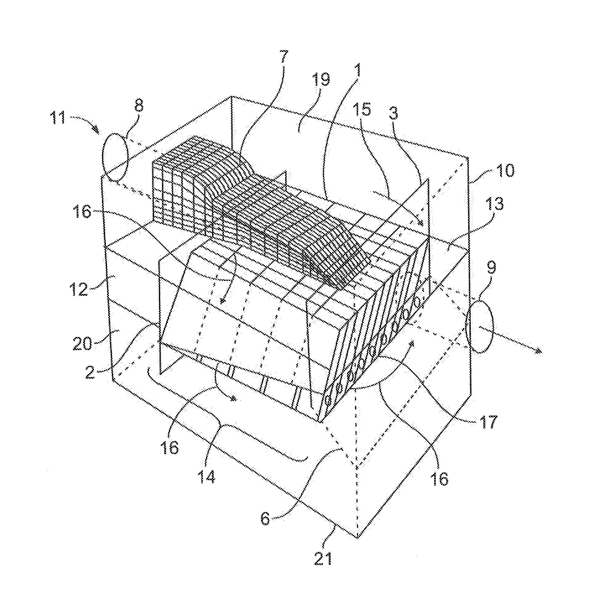
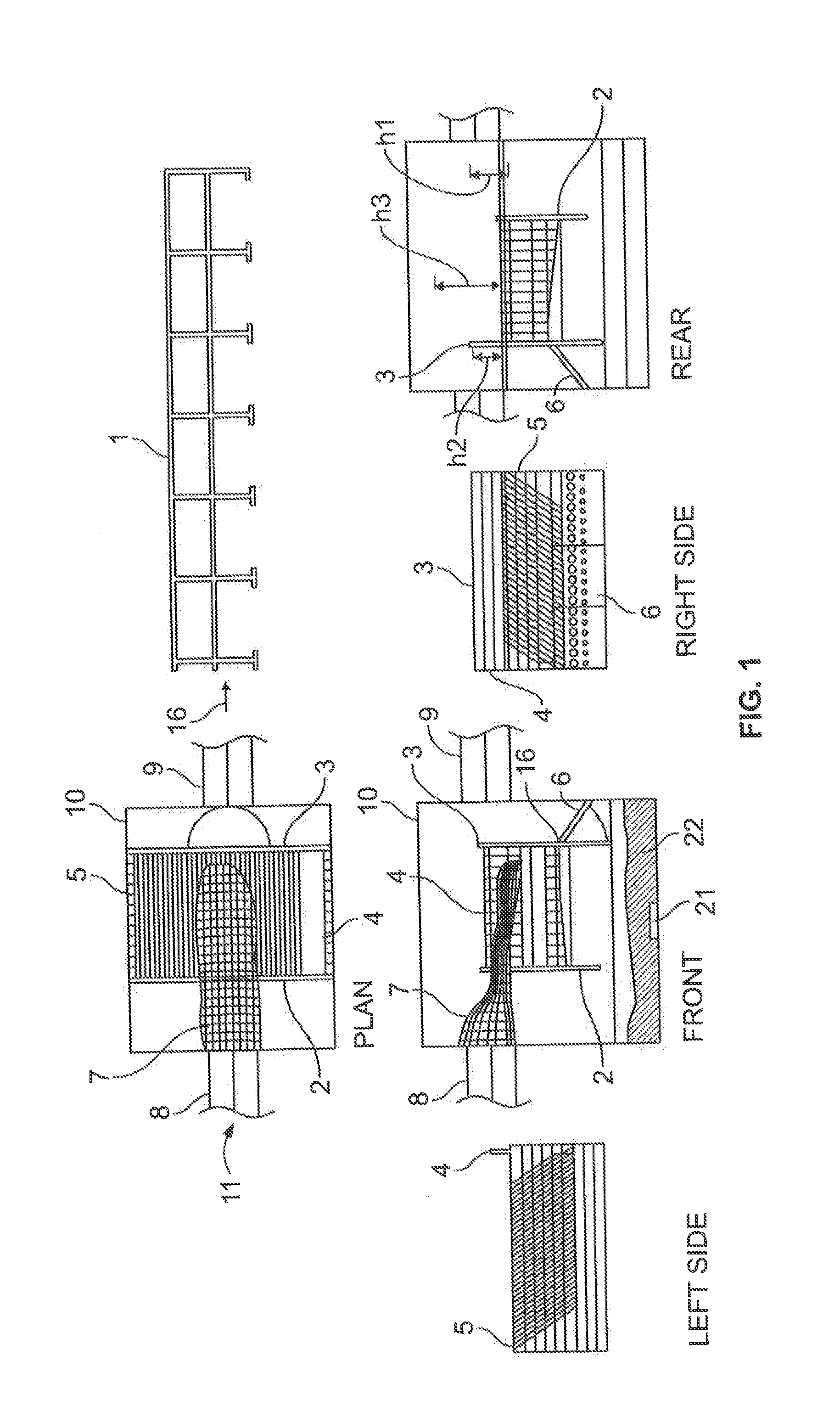
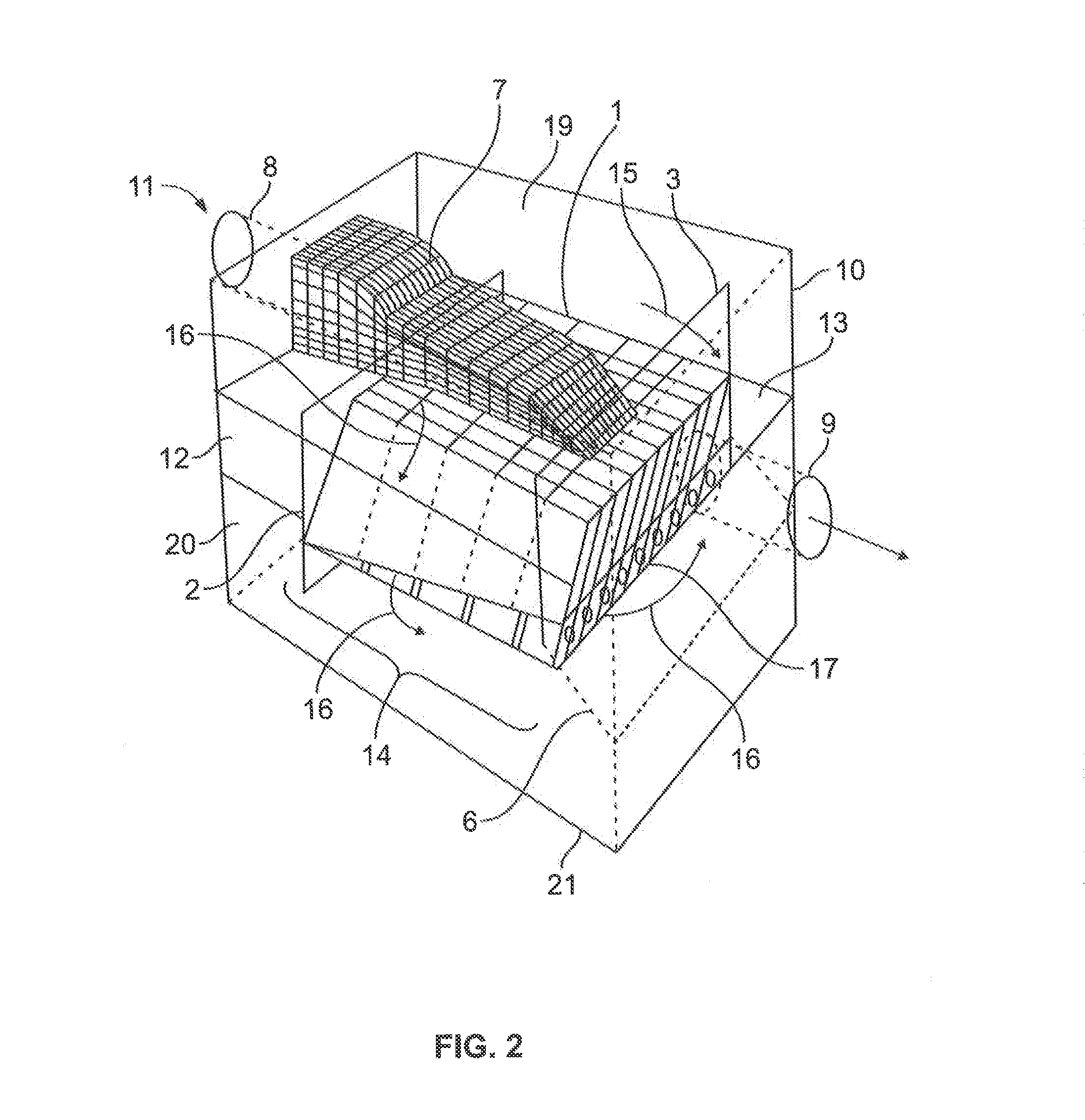
[0025]Theoretically, the Reynolds number could be balanced by increasing the flow rate by 48.8% in the ribbed cells. Prior art teaches the discharge of cleansed water at the top of the cell and sediment at the bottom of the cell. The new con-current flow pattern must deal with this and the method is shown in drawing 1 and drawing 2. The ribbed cells in drawing I are overlapped as shown in drawing 2) view A. The water flows parallel to the floor and ribs of the cell and reaches the bottom and turns towards the orifice openings in the hinged orifice baffle. The triangular extension provides a continuous path for the sediment to slide towards the sediment bunker. The vertical ribs act like flow separators inside the cell section but in the triangular zone the ribs are approximately 25% of the rib height and protect the sediment from being in the flow path of the cleansed water which now flows perpendicular to the ribs towards the orifice openings. This innovation preserves mixing of the cleansed water with the settled sediment when the two streams change directions and would otherwise re-suspend the sediment as it departs from multiple parallel overlapping sedimentation cells to a singular conduit leading to the orifices. The design takes advantage of the gravity induced stratification of the water and the sediment. The lighter water flows near the cell ceiling

Problems solved by technology

In the USA, surface water run-off quality is regulated by the Clean Water Act and affects the con

Method used


Image

  • Inclined plates for cso
  • Inclined plates for cso
  • Inclined plates for cso

Examples


Embodiment Construction

[0038]While this invention is susceptible of embodiments in many different shape and size, the present invention is shown and described in the attached drawings.

[0039]The purification goal of the inclined cells is to remove as much sediment by means of exposure of the flowing water to settling area provided by the cells. This creates a condition where the relative movement of the settling particle and the encapsulating water separate. The water and the particle move “En Masse” as a closed cell and only the density difference facilitates relocation of the particle within the cell. There must be equality of this condition throughout the inclined cell settling device to preserve the settling performance and repeatability of the performance. By maintaining a constant pressure head and placing orifices across the length of the hinged baffle and shaping matching the flow path length of all cells to its neighboring cells from the crest point of the dry-weather flow weir to the orifice, the...


PUM

PropertyMeasurementUnit
Flow rateaaaaaaaaaa
Lengthaaaaaaaaaa
Widthaaaaaaaaaa

Abstract

This device serves to improve water quality under gravity flow conditions. The water quality treatment device traps floating debris with replaceable netting, it contains oil spills and settles sediment in self-cleaning settling cells above a collection bunker inside a chamber. The device directs the water below the inclined cells, through the inclined cells, or over the inclined cells, depending on the inflow intensity. All inflowing water enters the net cavity and the net is supported by the inclined cell assembly. The pollutant collection surfaces are overlapping each other and aligned with the water flow direction. A hinged baffle with orifices controls the flow rate through the inclined cells. The netting is replaceable when filled with debris through an access opening in the ceiling of the chamber. The sediment bunker is cleaned through access openings in the ceiling from the chamber inflow side and the exit side.

Description

FIELD OF INVENTION[0001]A water quality treatment device and in particular a device for cleaning storm water that traps debris in storm water with replaceable netting while containing oil spills and settling sediment in self-cleaning settling lamellae or cells above a collection bunker inside a chamber.BACKGROUND OF THE INVENTION[0002]U.S. Pat. No. 3,706,384 (384 patent) in claim 1 teaches the flow distribution through a plurality of inclined plates, lamellae or cells in parallel to each other by means of entering the water into the lowermost side of the plates, lamellae or cells and discharging the water at the uppermost portion of the inclined plates, lamellae or cells. The '384 patent teaches the extension of the lamellae or cells to limit horizontal flow across the inclined lamellae or cells, U.S. Pat. No. 6,676,832 ('832 patent) teaches the use of inclined lamellae among other structural features including a dual chamber configuration for the treatment of surface water run-off ...

Claims


Application Information

Patent Timeline
IPC IPC(8): E02B8/02E03F1/00
CPCE03F1/00E02B8/023E03F5/16E02B5/085B01D21/0087B01D21/0045B01D21/0051B01D21/006B01D21/0039
Inventor MORAN, DENNIS R.TRNKA, WALTER C.BRUIJN, HANS DE
Owner FRESH CREEK TECH LLC
Why Eureka
Try Eureka