Wind turbine blade with plurality of longitudinally extending flow guiding device parts

a technology of longitudinal extension and wind turbine blade, which is applied in the direction of wind turbines, engine components, wind energy generation, etc., can solve the problems of reducing the load of the blade, increasing the financial gain, and increasing the load, so as to achieve easy and cheap manufacturing and huge structural advantages

Active Publication Date: 2017-07-04
LM GLASSFIBER
View PDF18 Cites 3 Cited by
  • Summary
  • Abstract
  • Description
  • Claims
  • Application Information

AI Technical Summary

Benefits of technology

[0012]Thus, the first flow guiding device group may comprise separate or modular parts in particular in the longitudinal direction of the blade. The modular construction makes the construction more flexible and reduces peel forces at the ends of the flow guiding device parts. Thus, the modular parts have a smaller tendency to break off from the surface of the blade.
[0062]In one advantageous embodiment, the base is formed of a flexible material. Thus, the bending stiffness of the base may be reduced and the base be bent to fit to the surface of the blade without introducing large stresses in a bond line between the base and the plate-shaped element. This may for instance be obtained by forming the base as a composite structure, such as polymer matrix material reinforced with glass fibres. The polymer matrix material may for instance be a polyurethane resin. Yet again, the base may be made of a polymer material, such as ABS plastic or polycarbonate.

Problems solved by technology

This again results in problems when having to mount the blade to the hub, and, moreover, this causes great loads during operation of the blade, such as storm loads, due to the large surface area of the blade.
Due to the circular cross-section, the root region does not contribute to the energy production of the wind turbine and, in fact, lowers this a little because of drag.
Therefore, even small changes to the overall performance of the blade may over the lifetime of a wind turbine blade accumulate to a high increase in financial gains, which surpasses the additional manufacturing costs relating to such changes.
However, the design proposed is very rigid due to the triangular shaped cross-section and consequently the flow guiding device has a tendency to separate from the surface of the blade, when the blade bends.

Method used


Image

  • Wind turbine blade with plurality of longitudinally extending flow guiding device parts
  • Wind turbine blade with plurality of longitudinally extending flow guiding device parts
  • Wind turbine blade with plurality of longitudinally extending flow guiding device parts

Examples


first embodiment

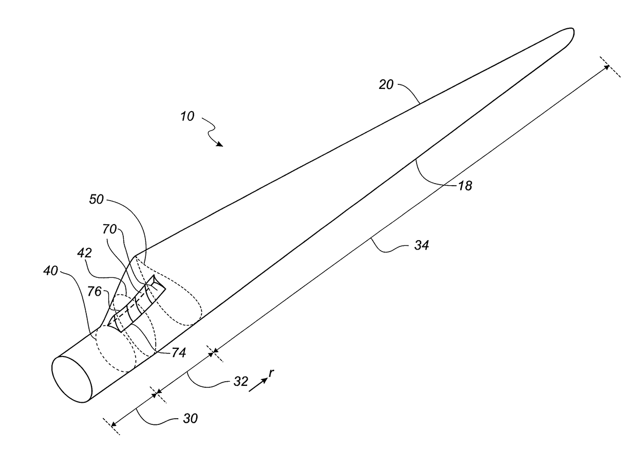
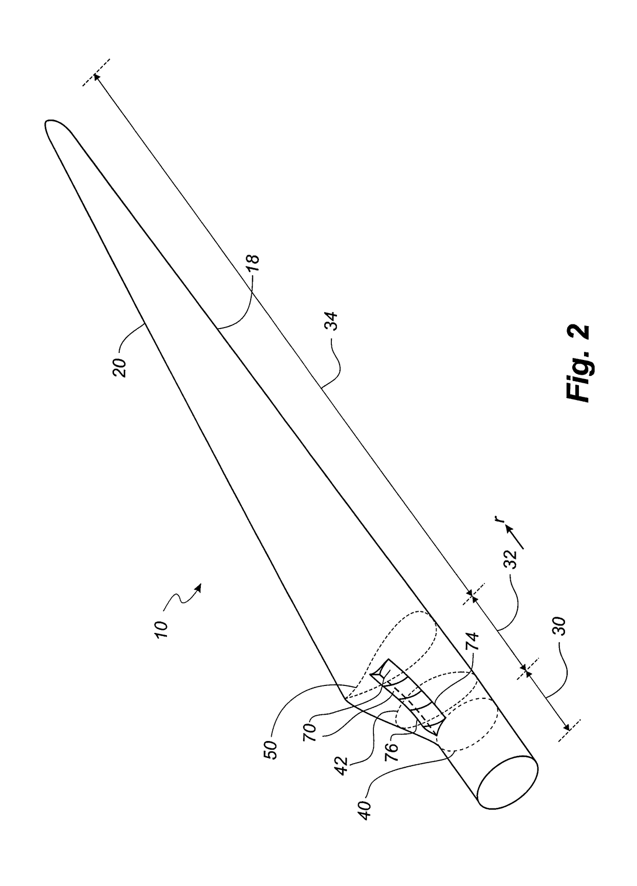
[0098]FIG. 2 shows a schematic view of a wind turbine blade 10 according to the invention. The wind turbine blade 10 has the shape of a conventional wind turbine blade and comprises a root region 30 closest to the hub, a profiled or an airfoil region 34 furthest away from the hub and a transition region 32 between the root region 30 and the airfoil region 34. The blade 10 comprises a leading edge 18 facing the direction of rotation of the blade 10, when the blade is mounted on the hub, and a trailing edge 20 facing the opposite direction of the leading edge 18.

[0099]The airfoil region 34 (also called the profiled region) has an ideal or almost ideal blade shape with respect to generating lift, whereas the root region 30 due to structural considerations has a substantially circular or elliptical cross-section, which for instance makes it easier and safer to mount the blade 10 to the hub. The diameter (or the chord) of the root region 30 is typically constant along the entire root are...

second embodiment

[0106]FIG. 19 shows a flow guiding device part 170′ according to the invention, wherein like numerals refer to like parts of the embodiment shown in FIG. 18. Therefore, only the difference between the two embodiments is described. In this embodiment, the plate-shaped element 197 is angled forward so that the plate-shaped element 197 forms a first angle φ with the base 190. Thus, the front surface 198 also faces slightly downwards towards the base 190 and the surface of the blade 10. When the front surface 198 during normal operation of the wind turbine is impacted by an oncoming airstream, an air pocket is formed in front of the front surface, which increases the pressure in front of the flow guiding device, and which guides the airflow around the flow guiding device 170′. Thus, an increased pressure is built up both in front of and behind the flow guiding device 170′. Thereby, the lift is increased along a large part of the blade section. The first angle φ is advantageously at leas...

third embodiment

[0119]FIG. 9 shows a schematic view of flow guiding device parts 370 according to the invention, seen from the side. In this embodiment, the flow guiding device parts 370 are partially overlapping in the longitudinal direction. Accordingly, one end of one flow guiding device part extends beyond a second end of a second flow guiding device part. The ends may be slightly angled as shown in the Figure.

[0120]FIG. 10 shows a schematic view of the third embodiment of flow guiding device parts 370 according to the invention, seen from the top. It can be seen the flow guiding device parts 370 are staggered in the longitudinal direction. The back surface of one flow guiding device part may abut the front surface of a second flow guiding device part, or there may be a small gap in the transverse direction of the blade.


PUM


Abstract

A wind turbine blade with a plurality of flow guiding device parts attached to a profiled contour on a pressure side of the blade is described. The longitudinally extending flow guiding device parts are grouped together to form a first flow guiding device group in the transition region of the blade.

Description

[0001]This is a National Phase Application filed under 35 U.S.C. 371 as a national stage of PCT / EP2010 / 065075, filed Oct. 8, 2010, and claiming the benefit from European Application No. 09172594.5, filed Oct. 8, 2009, the content of which is hereby incorporated by reference in its entirety.TECHNICAL FIELD[0002]The present invention relates to a blade for a rotor of a wind turbine having a substantially horizontal rotor shaft, said rotor comprising a hub, from which the blade extends substantially in a radial direction when mounted to the hub, the blade having a longitudinal direction with a tip end and a root end and a transverse direction, wherein the blade further comprises: a profiled contour including a pressure side and a suction side, as well as a leading edge and a trailing edge with a chord having a chord length extending there between, the profiled contour when being impacted by an incident airflow generating a lift, wherein the profiled contour is divided into: a root regi...

Claims


Application Information

Patent Timeline
Patent Type & Authority Patents(United States)
IPC IPC(8): F03D1/06
CPCF03D1/0641F05B2240/121F05B2240/301Y02E10/721F05B2240/305Y02E10/72
Inventor FUGLSANG, PETERBOVE, STEFANOVEMULAPATI, SUBRAHMANYAM VENKATALUND, BRIANJENSEN, LARS E.RADHAKRISHNAN, SREERAM KOTTUMUKLU
Owner LM GLASSFIBER
Why Eureka
Try Eureka