
Bolted joint assembly

a bolted joint and assembly technology, applied in the direction of threaded fasteners, rod connections, transportation and packaging, etc., can solve the problems of loosing the joint, catastrophic joint failure, and structure torque loss, and achieve the effect of reducing peeling force and high strength

Inactive Publication Date: 2011-11-10
FORD GLOBAL TECH LLC
View PDF20 Cites 3 Cited by
  • Summary
  • Abstract
  • Description
  • Claims
  • Application Information

AI Technical Summary

Benefits of technology

[0006]Embodiments of the present disclosure provide many advantages. For example, the reinforcement member may be hydroformed, which provides high strength to the anchor assembly. Further, the joint includes a bearing surface on a single metal (the nut surface); therefore, the joint does not introduce any torque loss. Further, the nut design compensates localized stresses at the threaded joint bearing surfaces. This reduces the peel force, and the joint is subjected mostly to shear stress. Moreover, the joint assembly is inexpensive and can be formed of any suitable material without departing from the scope of the present disclosure.

Problems solved by technology

In high impact situations, excessive loads may be asserted on this joint assembly causing a “peel stress” on the nut-bolt assembly, which in turn can loosen the joint or cause catastrophic joint failure.
Further, these structures experience torque losses due to the large bearing surfaces exposed to stresses.

Method used


Image

  • Bolted joint assembly
  • Bolted joint assembly
  • Bolted joint assembly

Examples


Embodiment Construction

[0010]Although the best mode for carrying out the invention has been described in detail, those familiar with the art to which this invention relates will recognize various alternative designs and embodiments for practicing the invention as described by the claims.

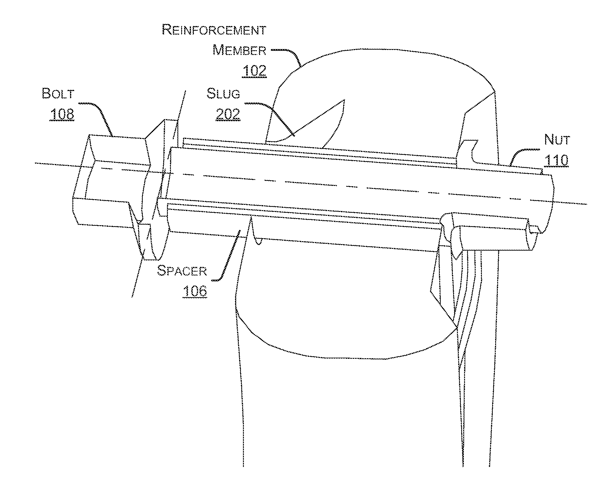
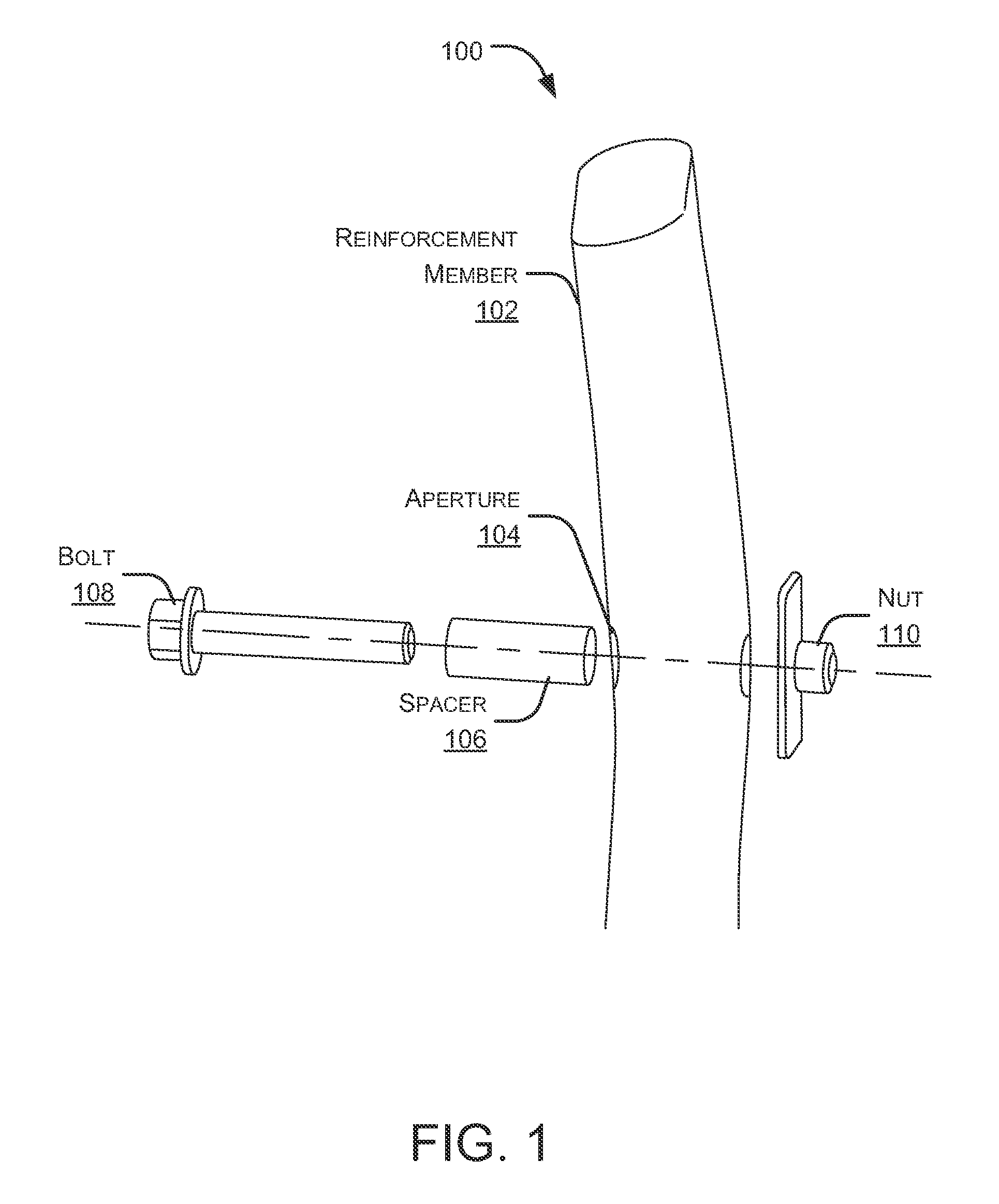
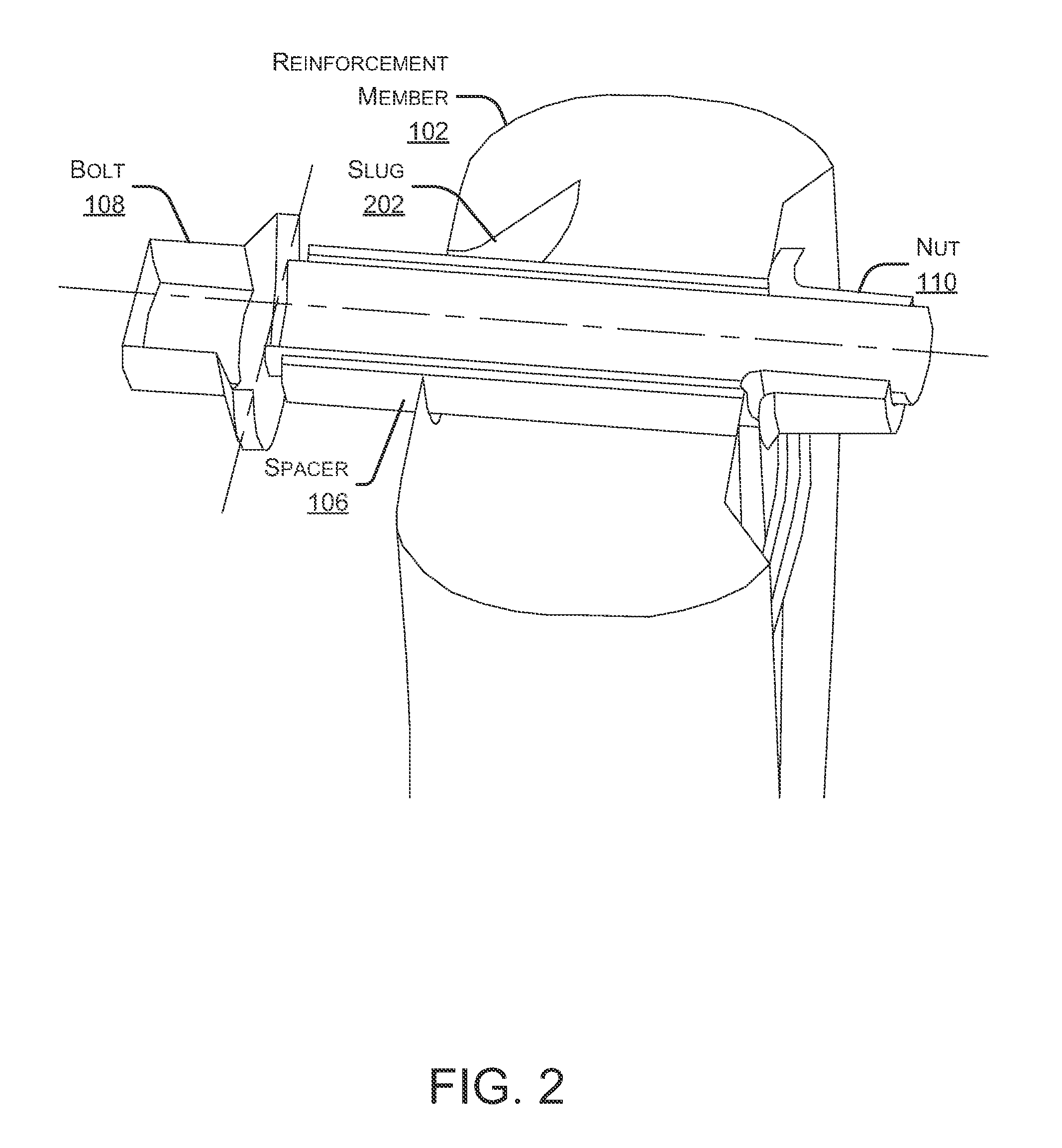
[0011]Embodiments of the present disclosure are directed towards an anchor assembly including a tubular reinforcement member. A nut-bolt assembly is fastened through the reinforcement member to increase the strength of the anchor assembly, reduce torque losses, and to reduce peeling stresses on the bolt.

[0012]In typical nut-bolt assemblies, joint failure requires a threshold force sufficient only to pull the bolt through the nut. The present disclosure, however, provides a design that can withstand a considerably higher threshold force, as the bolt is fastened through a reinforcement member; in this design, failure can only be realized if the applied force (from a collision, for example) is sufficient to force the bolt thr...


PUM


Abstract

A bolted joint assembly is described. The joint assembly includes a tubular reinforcement member for adding strength to the anchor assembly. The member having an aperture punched through-and-through the member substantially perpendicular to the longitudinal axis of the member. The anchor assembly further includes a hollow spacer tube extending through the aperture, the spacer diameter being substantially equal to the aperture diameter. Moreover, the assembly includes a bolt with a bolt head extended through the spacer. The bolt diameter is substantially equal to the spacer diameter. A nut threadably receives the anchor bolt.

Description

BACKGROUND OF THE INVENTION[0001]The present application relates generally to joint assemblies, and more particularly, to hydroformed reinforced joint assemblies.[0002]Typical bolted joints in automotive applications, such as seat belt anchorage, seat anchorage, and structural component mounts, are required to handle high loads. For example, legal standards in certain jurisdictions require seatbelt anchor bolts to support a load, sufficient to ensure that they do not fail in the event of a sudden large force, imposed, for example, by emergency braking or an accident.[0003]Generally, for such anchor applications, a nut-bolt joint assembly is utilized. For example, in a seatbelt application, the bolt is generally secured to a structural panel of the vehicle side pillar, threaded into an anchor nut. In high impact situations, excessive loads may be asserted on this joint assembly causing a “peel stress” on the nut-bolt assembly, which in turn can loosen the joint or cause catastrophic ...

Claims


Application Information

Patent Timeline
Patent Type & Authority Applications(United States)
IPC IPC(8): F16B7/18
CPCB60N2/682Y10T403/3961F16B37/061
Inventor STOJKOV, DRAGANMORGANS, SHAWNFREEMAN, MIKE
Owner FORD GLOBAL TECH LLC
Learn More