
Micro-electro-mechanical device with compensation of errors due to disturbance forces, such as quadrature components

a micro-electromechanical and disturbance force technology, applied in the direction of microstructural devices, microstructure devices, microstructure technology, etc., can solve the problems of non-ideal electro-mechanical interactions, manufacturing defects and process spread are potentially inevitable sources of noise, and the oscillation direction of the driving mass does not perfectly match the degrees of freedom desired, so as to reduce the incidence of quadrature oscillation, stabilize the effect, and reduce the dynamic response of the suspended mass

Active Publication Date: 2017-07-04
STMICROELECTRONICS SRL
View PDF23 Cites 6 Cited by
  • Summary
  • Abstract
  • Description
  • Claims
  • Application Information

AI Technical Summary

Benefits of technology

This patent aims to reduce the problem of unwanted movements in MEMS devices. The invention introduces a dynamic absorber that can compensate for these unwanted movements by tuning the damping mass to the specific forces that cause them. This results in a more stable and controlled system.

Problems solved by technology

However, MEMS gyroscopes have a complex structure and frequently have non-ideal electro-mechanical interactions between the suspended mass and the supporting body.
For instance, manufacturing defects and process spread are potentially inevitable sources of noise, the effect whereof is unforeseeable.
A common defect depends upon the fact that the oscillation direction of the driving mass does not perfectly matches the degrees of freedom desired in the design stage.
This defect is normally due to imperfections in the elastic connections between the suspended mass and the supporting body and causes onset of a force directed along the detection degree of freedom of the angular velocity.
In some cases, the quadrature components are so large that they may not simply be neglected without introducing significant errors.
However, in many cases, the problem is not completely solved, since the amplitude of the quadrature oscillations may vary during the life of the device.
In particular, the supporting body may be subject to deformations due to mechanical stresses or temperature variations.
In turn, the deformations of the supporting body may cause unforeseeable variations in the movements of the masses and, consequently, in the quadrature components, which are no longer effectively compensated.

Method used


Image

  • Micro-electro-mechanical device with compensation of errors due to disturbance forces, such as quadrature components
  • Micro-electro-mechanical device with compensation of errors due to disturbance forces, such as quadrature components
  • Micro-electro-mechanical device with compensation of errors due to disturbance forces, such as quadrature components

Examples


Embodiment Construction

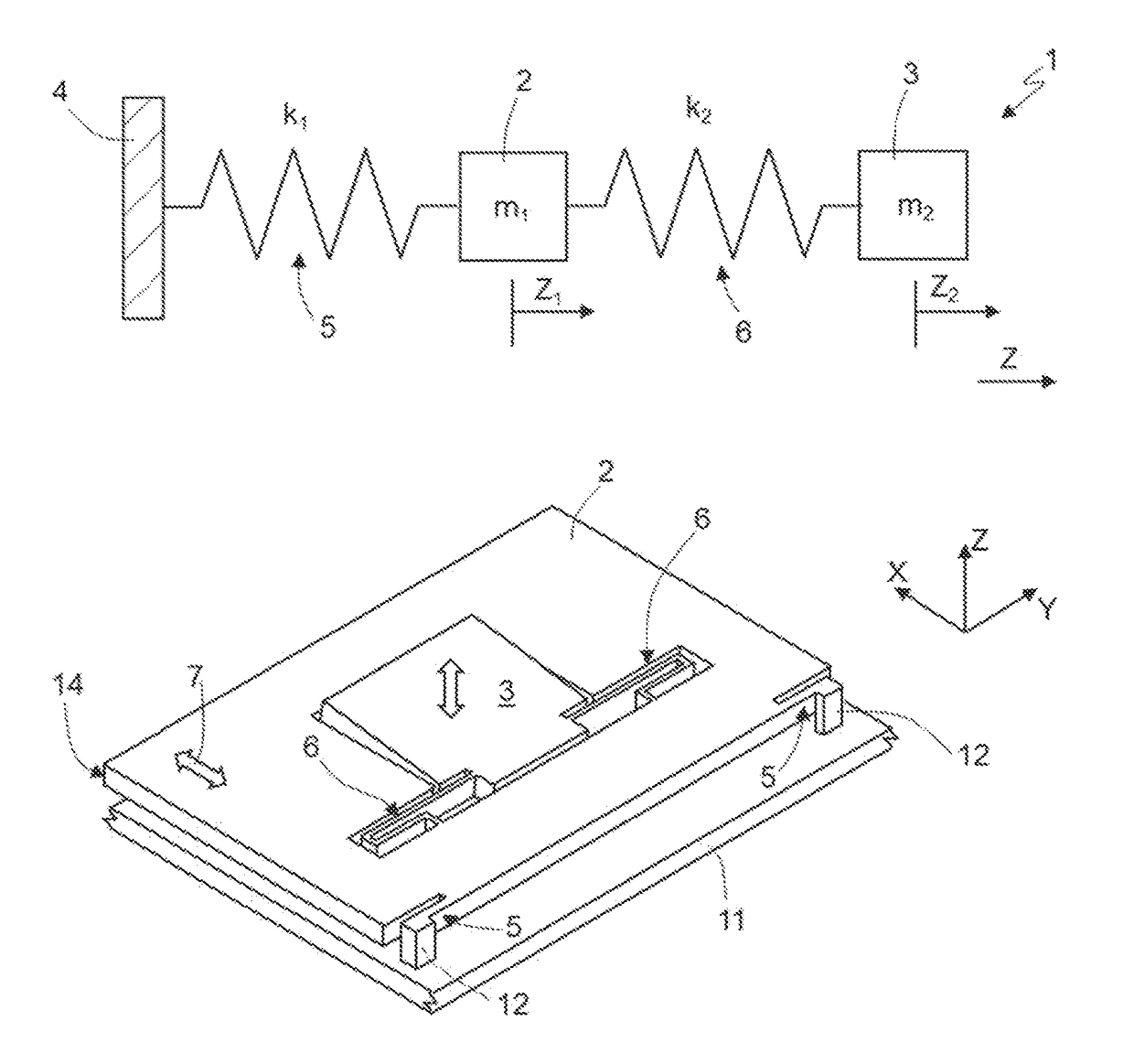
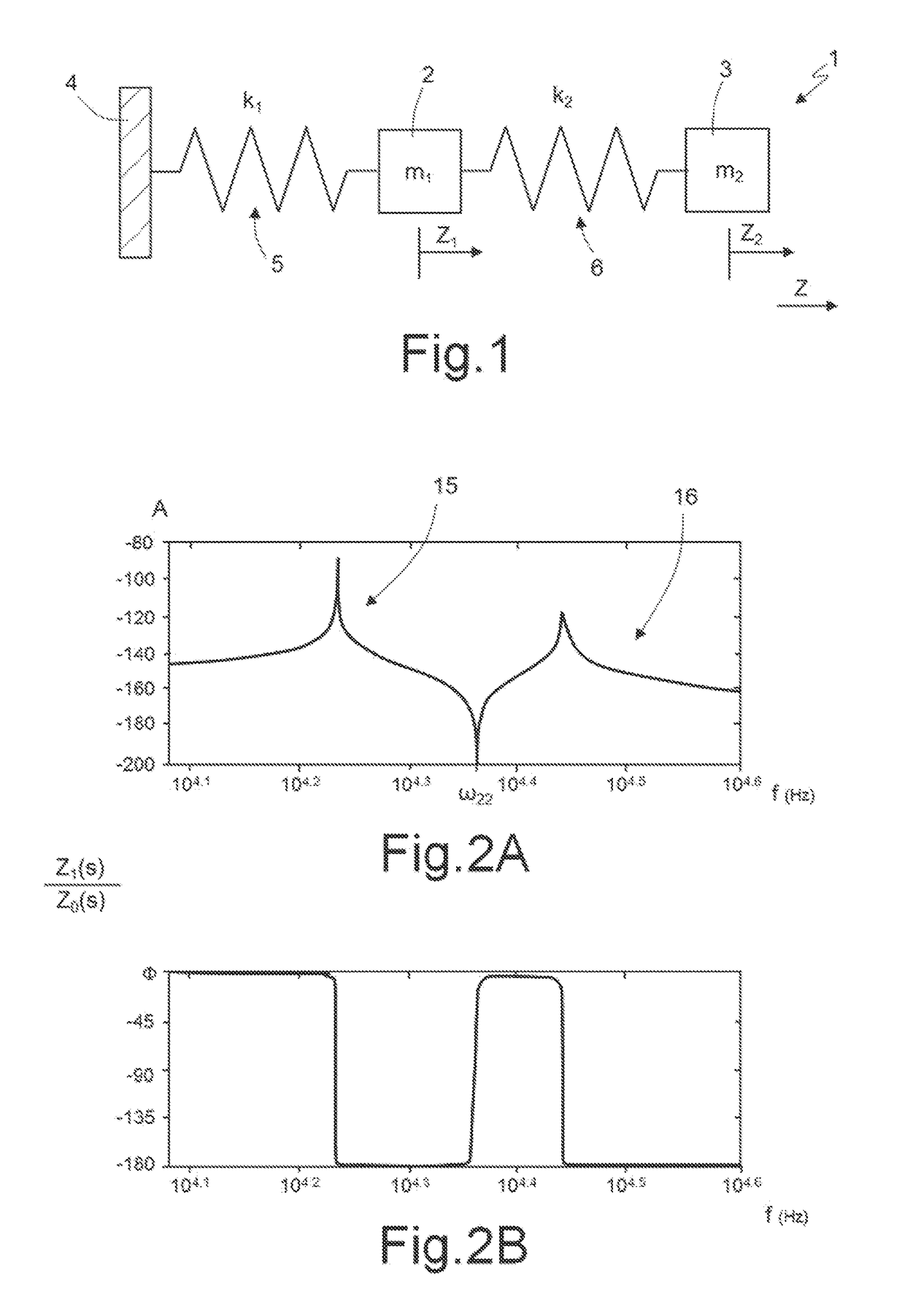
[0024]For an understanding of aspects of the present disclosure, reference will be made to FIG. 1, showing a block diagram of a MEMS device 1, such as a gyroscope, having two degrees of freedom (even though the following considerations also apply to systems having N degrees of freedom).

[0025]FIG. 1 schematically shows a MEMS device 1 represented schematically in its basic elements as regards the dynamic behavior according to one degree of freedom (displacement along an axis Z in the presence of undesired components, for example, quadrature components, along this axis), thus neglecting any movements in other directions. The considerations hereinafter are thus aimed at highlighting the conditions whereby the effect of the undesired force in the considered direction is canceled out.

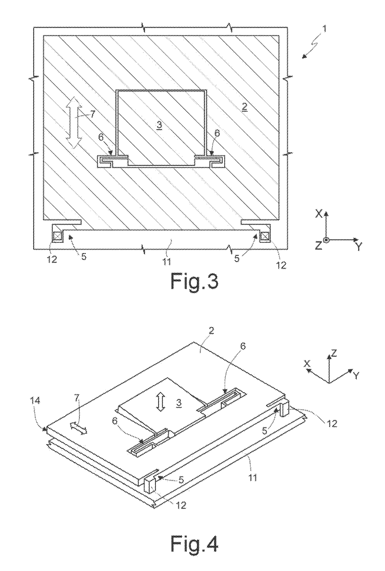
[0026]The MEMS device 1 comprises a suspended mass 2 and a damping mass 3. The suspended mass 2 is constrained to a supporting body 4 through a first system of springs 5 having elastic constant k1 and to the...


PUM


Abstract

MEMS device having a support region elastically carrying a suspended mass through first elastic elements. A tuned dynamic absorber is elastically coupled to the suspended mass and configured to dampen quadrature forces acting on the suspended mass at the natural oscillation frequency of the dynamic absorber. The tuned dynamic absorber is formed by a damping mass coupled to the suspended mass through second elastic elements. In an embodiment, the suspended mass and the damping mass are formed in a same structural layer, for example of semiconductor material, and the damping mass is surrounded by the suspended mass.

Description

BACKGROUND[0001]Technical Field[0002]The present disclosure relates to a micro-electro-mechanical device with compensation of errors due to disturbance forces, such as quadrature components.[0003]Description of the Related Art[0004]As is known, MEMSs (Micro-Electro-Mechanical Systems) are used in an increasingly widespread way in different applications, due to their small dimensions, costs compatible with consumer applications, and their increasing reliability. In particular, with this technology inertial sensors are manufactured, such as microintegrated gyroscopes and electro-mechanical oscillators.[0005]MEMSs of this type are generally based upon micro-electro-mechanical structures comprising a supporting body and at least one mobile mass coupled to the supporting body through springs or “flexures”. The springs are configured for enabling the mobile mass to oscillate with respect to the supporting body according to one or more degrees of freedom. The mobile mass is capacitively co...

Claims


Application Information

Patent Timeline
Patent Type & Authority Patents(United States)
IPC IPC(8): G01C19/00G01C19/5733B81B3/00G01C19/5712G01C19/5747
CPCG01C19/5712B81B3/0018G01C19/5733G01C19/5747B81B7/02G01C19/5776B81B2203/0163B81B3/0086B81B2201/025
Inventor FALORNI, LUCA GIUSEPPEVALZASINA, CARLOCARMINATI, ROBERTOTOCCHIO, ALESSANDRO
Owner STMICROELECTRONICS SRL
Learn More