Power milling machine
a power milling machine and power technology, applied in the field of milling machines, can solve the problem that replacing the tool requires only a small installation spa
- Summary
- Abstract
- Description
- Claims
- Application Information
AI Technical Summary
Benefits of technology
Problems solved by technology
Method used
Image
Examples
Embodiment Construction
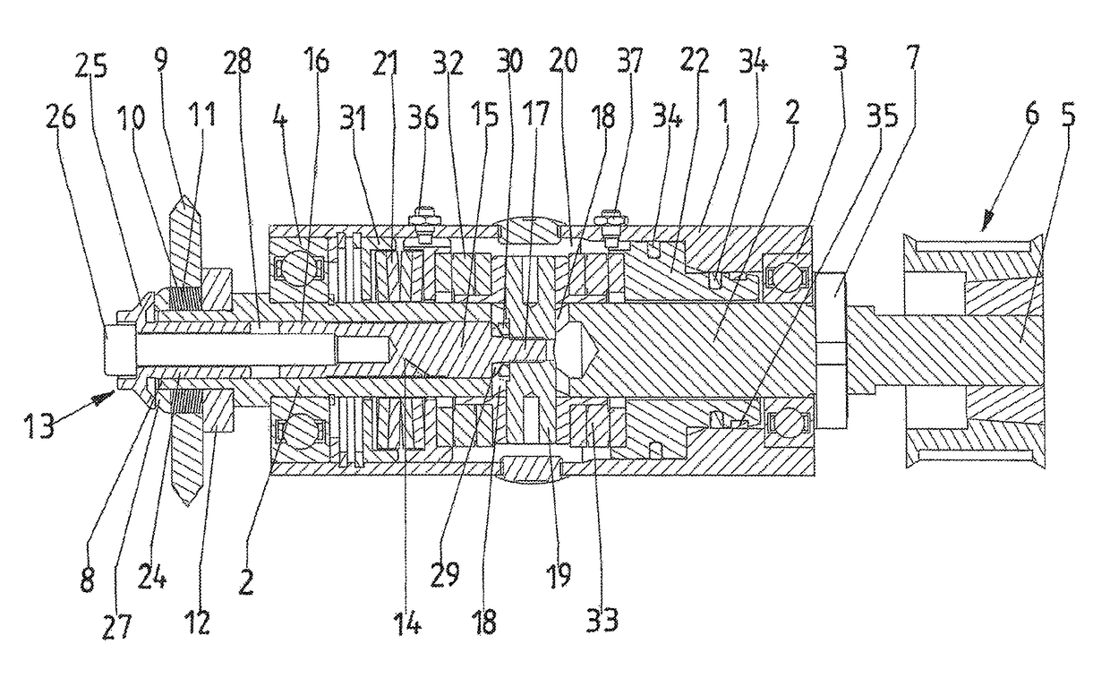
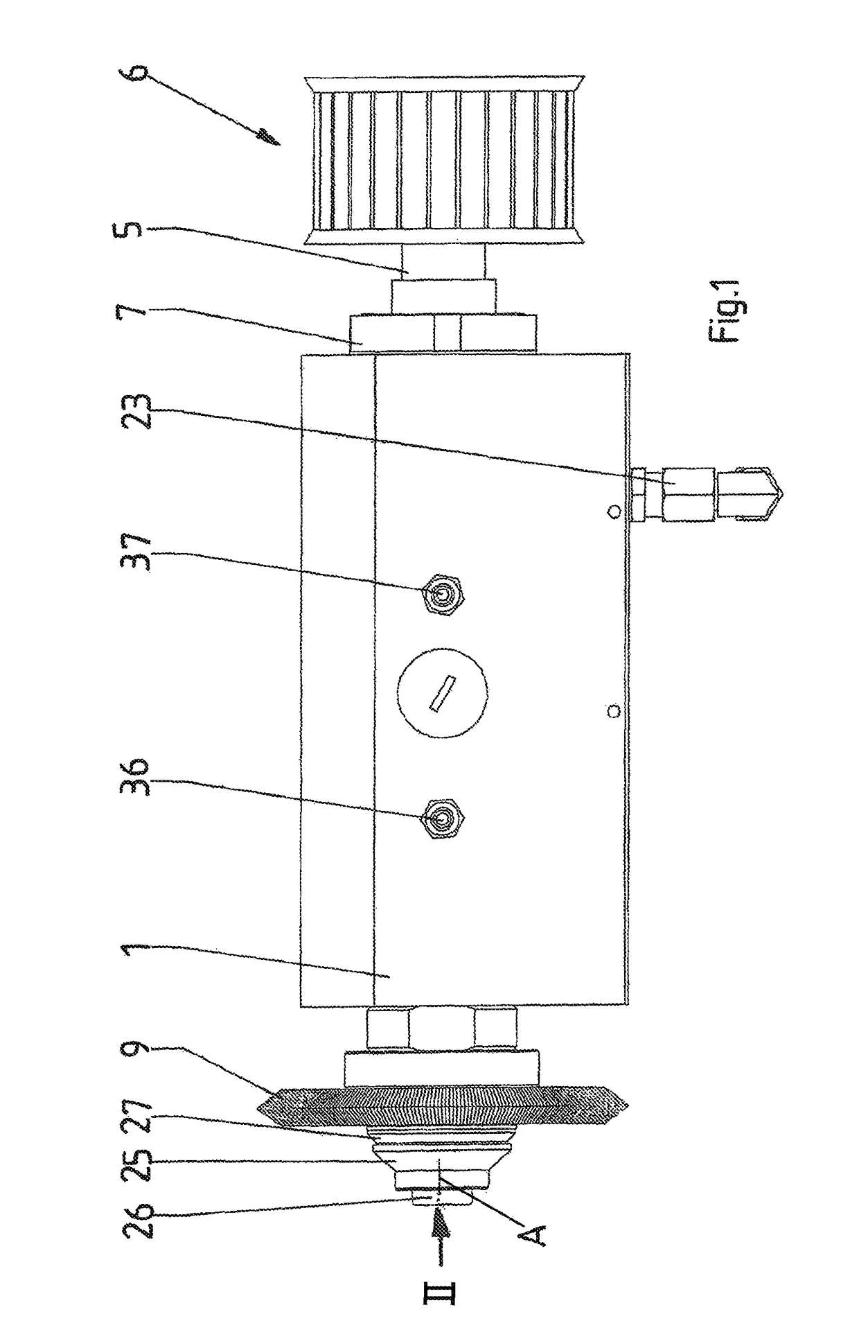
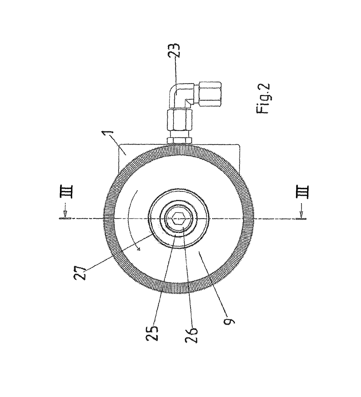
[0027]As seen in FIGS. 1-3 a milling machine for sharpening blades of a root-vegetable processor has a drive shaft 2 rotatable about an axis A in a housing 1. The drive shaft 2 is carried on bearings 3, 4, here roller bearings with inner and outer races provided at the ends of the housing 1. A rear end of the drive shaft 2 projects axially rearward out of the housing and carries means 6 for coupling to an unillustrated drive motor. In the embodiment, the means 6 is, for example, a toothed wheel adapted to be connected by an unillustrated toothed belt and the drive motor. A snap ring 7 is set in the rear end 5 to axially secure the shaft 2 in the housing 1.
[0028]A front end 8 of the drive shaft 2 projects axially forward from the housing 1 and is supported by the bearing 4. This front end 8 carries a milling tool 9, for example a cutting disk. The tool 9 has a central cylindrical mounting hole 10 carried on the shaft 2 via a stack 11 of washers carried on the shaft 2. When installed,...
PUM
| Property | Measurement | Unit |
|---|---|---|
| diameter | aaaaa | aaaaa |
| rotation | aaaaa | aaaaa |
| axial force | aaaaa | aaaaa |
Abstract
Description
Claims
Application Information
 - R&D
- Intellectual Property
- Life Sciences
- Materials
- Tech Scout
- Unparalleled Data Quality
- Higher Quality Content
- 60% Fewer Hallucinations
Browse by: Latest US Patents, China's latest patents, Technical Efficacy Thesaurus, Application Domain, Technology Topic, Popular Technical Reports.
© 2025 PatSnap. All rights reserved.Legal|Privacy policy|Modern Slavery Act Transparency Statement|Sitemap|About US| Contact US: help@patsnap.com


