

Tube and shock absorber
a technology of shock absorber and tube, which is applied in the direction of shock absorbers, manufacturing tools, transportation and packaging, etc., can solve the problems of affecting the durability of the sealing rings fitted into the sealing ring grooves, and the acute raised portions are not easily recognized, so as to enhance the durability of the sealing rings. the effect of the sealing rings
- Summary
- Abstract
- Description
- Claims
- Application Information
AI Technical Summary
Benefits of technology
Problems solved by technology
Method used
Image

Examples
Embodiment Construction
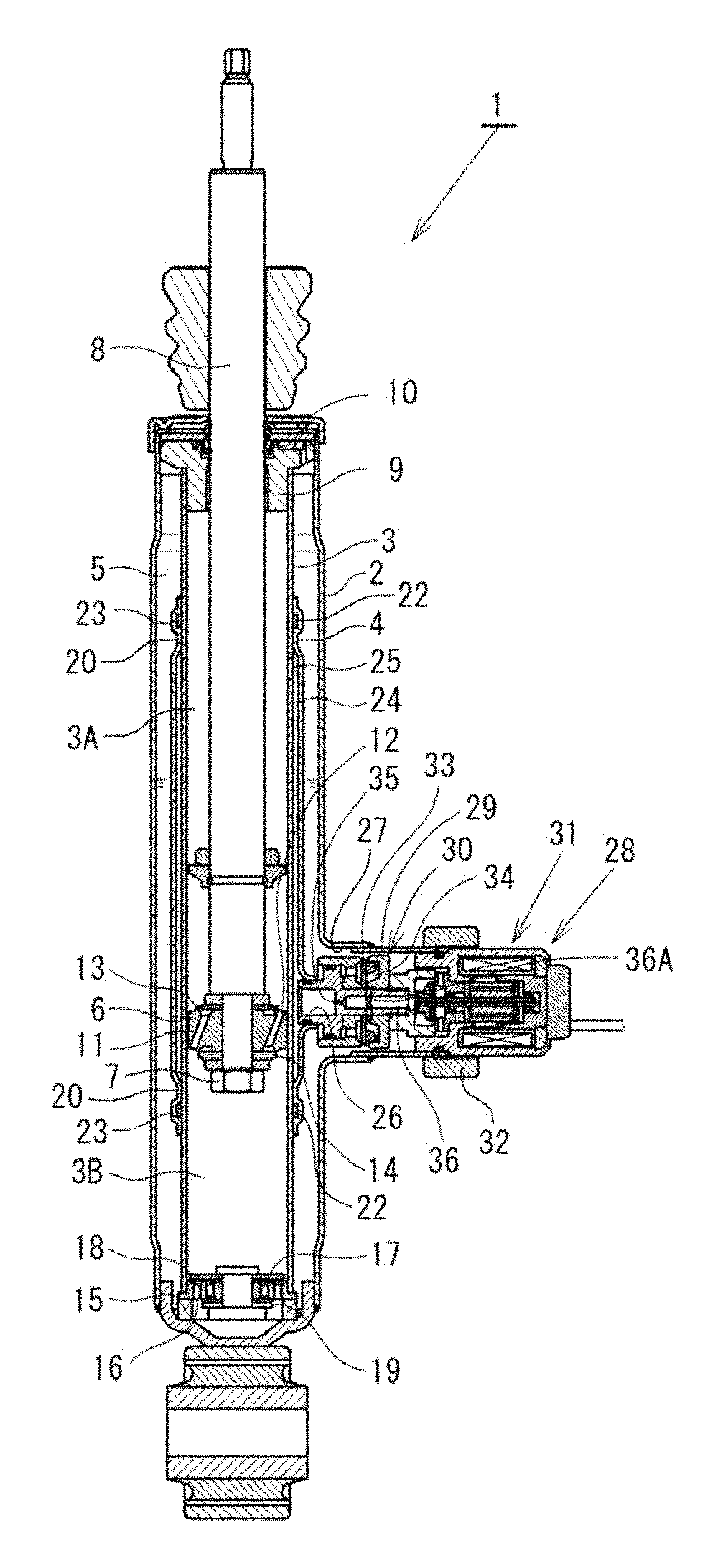
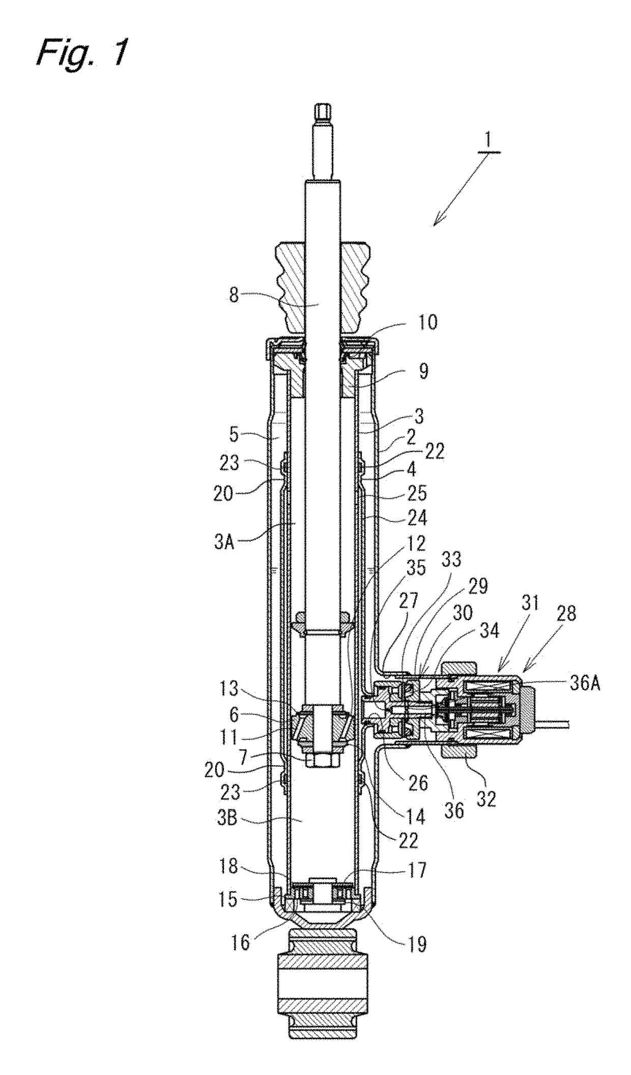
[0019]With reference to the accompanying drawings, description is made of an embodiment of the present invention. First, description is made of a damping force adjustable hydraulic shock absorber 1 (hereinafter referred to as “shock absorber 1”) of this embodiment. Note that, for the sake of convenience of description, the up-and-down direction in FIG. 1 is defined as an up-and-down direction of the shock absorber 1. As illustrated in FIG. 1, the shock absorber 1 has a double tube structure including an outer tube 2 and a cylinder 3, and a separator tube 4 (tube) is provided to surround an outer periphery of the cylinder 3. Further, a reservoir 5 that is an annular space is formed at an outer portion of the separator tube 4 between the outer tube 2 and the cylinder 3.
[0020]A piston 6 is inserted into the cylinder 3 in a slidable manner. The piston 6 is fixed to one end of a piston rod 8 with a nut 7, and partitions an inside of the cylinder 3 into a first chamber 3A and a second cha...
PUM
| Property | Measurement | Unit |
|---|---|---|
| inclination angle | aaaaa | aaaaa |
| inclination angle | aaaaa | aaaaa |
| inclination angle | aaaaa | aaaaa |
Abstract
Description
Claims
Application Information