
Data collection system and method that detect electronic device displays via fresnel patterns

a data collection system and electronic device technology, applied in the field of readers, can solve the problems of limiting affecting the accuracy and the illumination provided by the data collection system is not compatible with the reading mode of the diffuse mode, so as to achieve the effect of reliably detecting and maximizing the performance of optical code or symbol reading

Active Publication Date: 2017-07-18
DATALOGIC ADC
View PDF15 Cites 6 Cited by
  • Summary
  • Abstract
  • Description
  • Claims
  • Application Information

AI Technical Summary

Benefits of technology

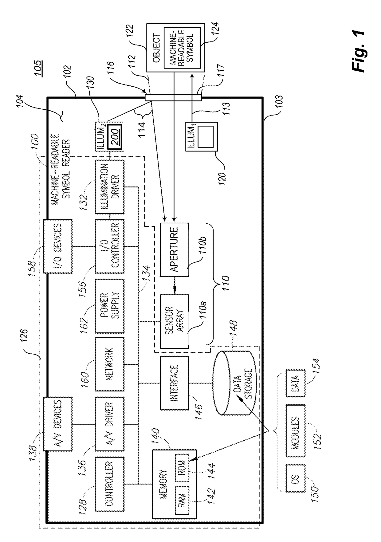
[0011]The described data collection methods and data collection systems allow efficient use of digital imaging resources to maximize performance of optical code or symbol reading on non-electronic media (e.g., diffuse reflection optical codes or symbols) by reliably detecting a presence or absence of a glass display of an electronic device (e.g., tablet computers, smartphones, smartwatches, personal digital assistants, electronic readers). This allows the data collection system (e.g., machine-readable symbol reader) to only switch from a higher throughput performance mode (i.e., diffuse reading mode) to a lower throughput performance mode (i.e., reflective reading mode) for reading from the display screen of the electronic device when such a display screen is actually present in a field of view of the data collection system.
[0012]Typically, digital imaging data collection systems (e.g., machine-readable symbol readers) read mainly diffusely reflecting codes or symbols printed on labels or directly on objects (e.g., retail item packaging). When used in this diffuse reading mode, the data collection system provides active illumination (e.g., strobed illumination) from a primary illumination source, coupled with a short imager exposure time to eliminate motion blur. This mode allows the data collection system to read codes or symbols on items moving at high speed.
[0015]An alternative method that might be used to avoid this problem is to look for bright image areas which are the result of specular reflections from the display screen of an electronic device. This method is fraught with problems, as there are many specularly reflective retail packages (e.g., plastic bags, metal cans, coated cardboard, coated paper) which create bright areas in an image, but which do not correspond to the presence of a display screen of an electronic device. Such an approach would tend to falsely force the data collection system into the long exposure, low-throughput mode too often, thereby significantly reducing data collection system performance.
[0016]The approach described herein maximizes performance of the data collection system, while allowing improved reading of information presented on display screens of electronic devices without adding any substantial hardware or product cost.
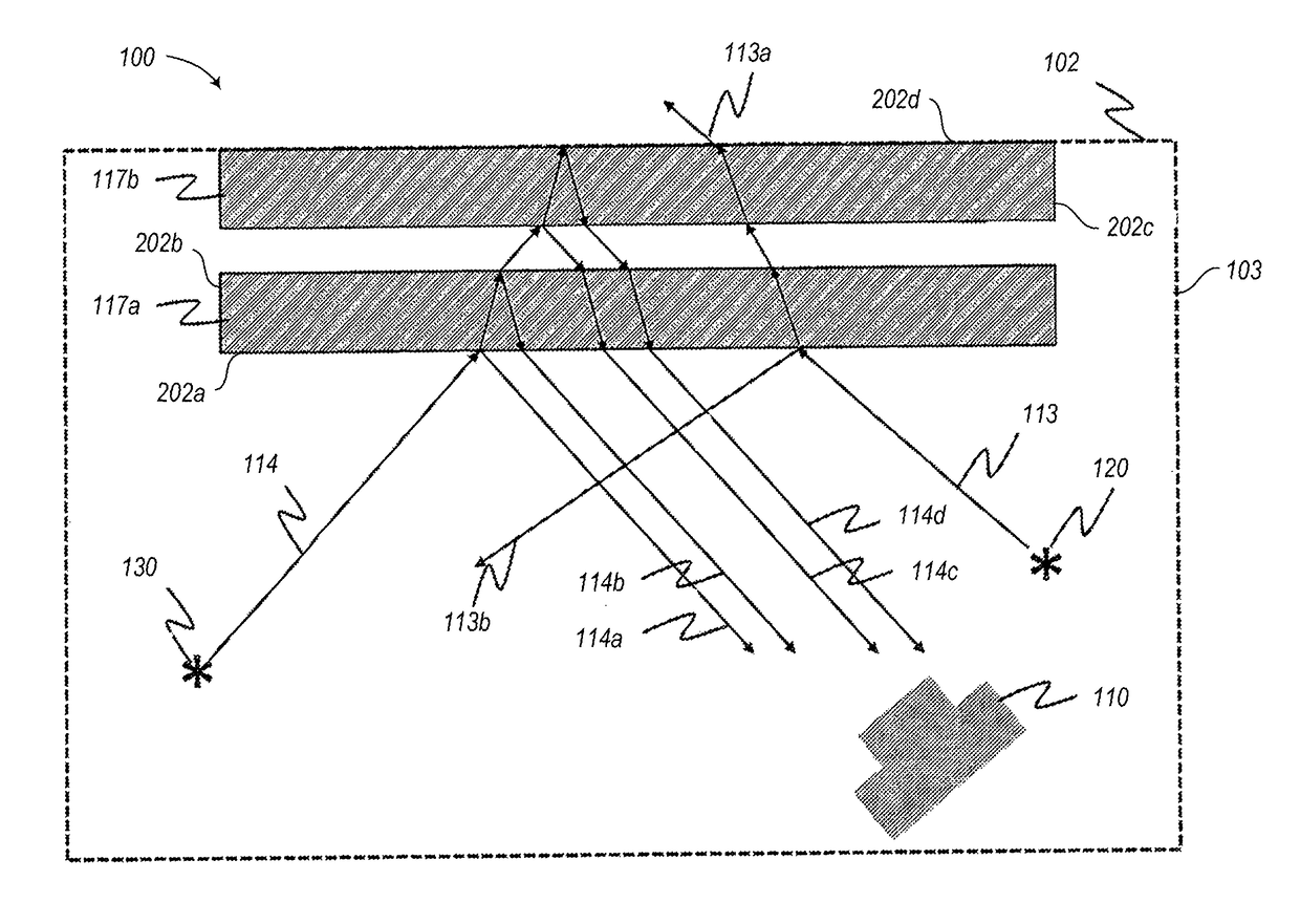
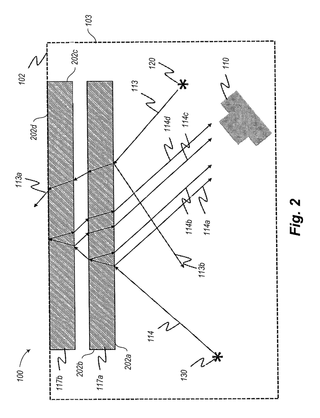
[0019]2. Flat optical materials allow preservation of high quality images upon reflection, acting as a form of mirror.
[0034]Switching between a first operational mode of the data collection system and a second operational mode of the data collection system may include causing the primary illumination source to at least temporarily stop providing illumination and at least temporarily causing an increase in exposure time.

Problems solved by technology

Unfortunately, in order to read optical codes or symbols presented via display screens of electronic devices such as those used in cell phones or electronic tablets, the optimum exposure conditions are not compatible with those of the diffuse reading mode.
When reading from a display screen, the illumination provided by the data collection system does not improve the contrast of the self-illuminated display screen, and may actually “blind” the imager if the surface of the display screen is tilted to reflect the illumination directly back into the imager (specular reflection).
Increasing the exposure time means that fewer image frames per second are available for decode, limiting overall throughput of the data collection system.

Method used


Image

  • Data collection system and method that detect electronic device displays via fresnel patterns
  • Data collection system and method that detect electronic device displays via fresnel patterns
  • Data collection system and method that detect electronic device displays via fresnel patterns

Examples


Embodiment Construction

[0047]In the following description, certain specific details are set forth in order to provide a thorough understanding of various disclosed embodiments. However, one skilled in the relevant art will recognize that embodiments may be practiced without one or more of these specific details, or with other methods, components, materials, etc. In other instances, well-known structures associated with the technology have not been shown or described in detail to avoid unnecessarily obscuring descriptions of the embodiments.

[0048]Unless the context requires otherwise, throughout the specification and claims that follow, the word “comprising” is synonymous with “including,” and is inclusive or open-ended (i.e., does not exclude additional, unrecited elements or method acts).

[0049]Reference throughout this specification to “one embodiment” or “an embodiment” means that a particular feature, structure or characteristic described in connection with the embodiment is included in at least one em...


PUM


Abstract

A control subsystem determines based on the characteristics of light from a secondary illumination source reflected off optics of a data collection device whether a display screen of an electronic device (e.g., smartphone, smartwatch, tablet computer) are in a field of view of the data collection device, and switches operational modes accordingly. Thus, the control subsystem can employ a Fresnel pattern for such determination. The data collection device can operate in a diffuse reading mode, characterized by active illumination and / or relatively fast exposure times. The data collection device can operate in a reflective reading mode, characterized by a lack of active illumination and / or relatively slow exposure times. Characteristics can include the number of reflections versus a number of air-substrate interfaces and / or a relative intensity of the reflections produced by successive air-substrate interfaces in a path of the light.

Description

BACKGROUND[0001]Technical Field[0002]The present disclosure relates to readers to read machine-readable symbols.[0003]Description of the Related Art[0004]Machine-readable symbols encode information in a form that can be optically read via an appropriately configured machine-readable symbol reader or scanner. Machine-readable symbols take a variety of forms, the most commonly recognized form being the linear or one-dimensional barcode symbol. Other forms include two-dimensional machine-readable symbols such as stacked code symbols, and area or matrix code symbols. These machine-readable symbols are typically composed of patterns of high and low reflectance areas. For instance, a barcode symbol may comprise a pattern of black bars on a white background. Also for instance, a two-dimensional symbol may comprise a pattern of black marks (e.g., bars, squares or hexagons) on a white background. Machine-readable symbols are not limited to being black and white, but may comprise two other co...

Claims


Application Information

Patent Timeline
Patent Type & Authority Patents(United States)
IPC IPC(8): G06F17/00G06K7/14G06K7/10
CPCG06K7/1413G06K7/10722G06K7/1095
Inventor MCQUEEN, ALEXANDER M.
Owner DATALOGIC ADC
Learn More