
Imaging apparatus and imaging method

a technology of imaging apparatus and image, which is applied in the direction of color television details, television system details, television systems, etc., can solve the problems of image quality lowering, image flicker, image flicker, etc., and achieve the effect of limiting the lowering of image quality

Active Publication Date: 2017-07-18
OM DIGITAL SOLUTIONS CORP
View PDF4 Cites 15 Cited by
  • Summary
  • Abstract
  • Description
  • Claims
  • Application Information

AI Technical Summary

Benefits of technology

[0009]An object of the present invention is to provide an imaging apparatus and an imaging method that limit lowering of image quality of an image that is taken while a zoom operation is in progress.

Problems solved by technology

However, whereas there is delay in movement due to the fact that an aperture is driven mechanically, since electronic shutter speed and ISO sensitivity are electrically controlled there is almost no time lag in an operation of changing these values.
As a result a time difference arises until an exposure it is desired to set is reached, and flicker arises in images for a movie or live view display, resulting in a visually undesirable screen.
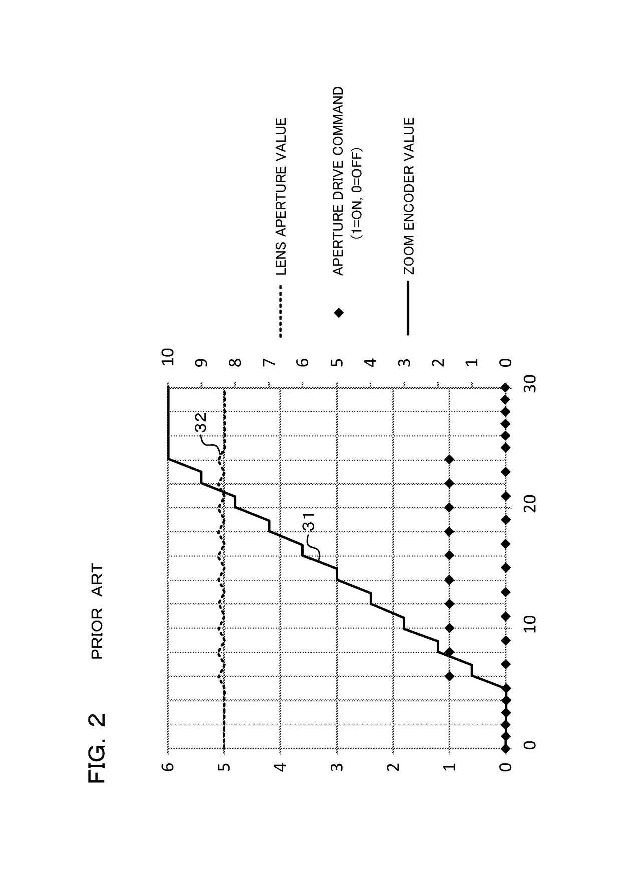
However, it is difficult to get a predicted value and actual aperture value to coincide completely, and as a result exposure fluctuations will arise at the time of movie shooting and at the time of live view display, causing image flicker.
Also, in the case where a zoom operation is carried out during movie recording, if an aperture operation is carried out in order to keep the aperture value (FNo) fixed, there is a problem that flicker will arise in the image and image quality is lowered.

Method used


Image

  • Imaging apparatus and imaging method
  • Imaging apparatus and imaging method
  • Imaging apparatus and imaging method

Examples


Embodiment Construction

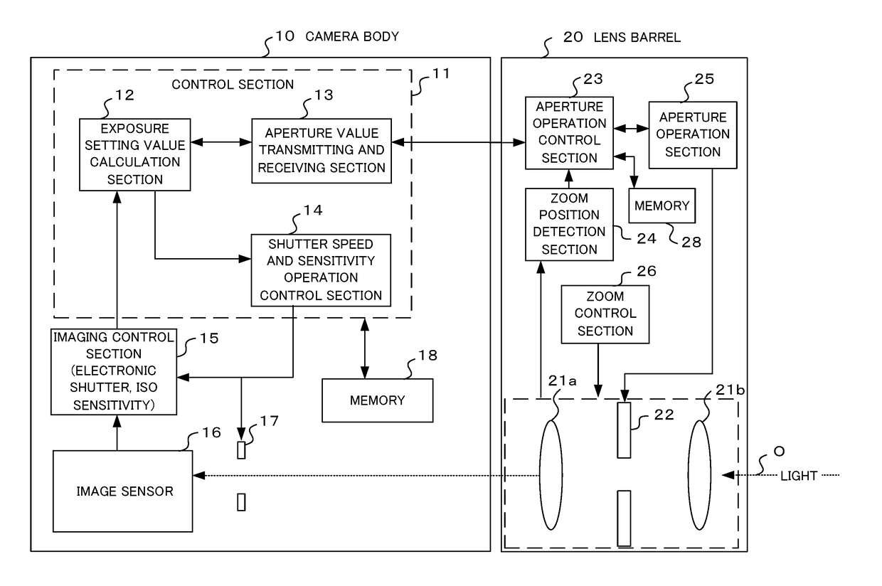
[0018]An example where a digital camera is adopted as one embodiment of the present invention will be described in the following. This digital camera has an imaging section, with a subject image being converted to image data by this imaging section, and the subject image being subjected to live view display on a display section arranged on the rear surface of the camera body or in an electronic viewfinder, based on this converted image data. A photographer determines composition and shooting timing while observing the live view display. If a movie button or the like is operated, recording of image data for a movie is commenced, and if the movie button or the like is operated again recording of image data for a movie is finished. It is also possible to shoot still pictures by operating a release button. Still picture and movie image data that has been stored in a storage medium can be subjected to playback display on a display section if playback mode is selected.

[0019]Also, the came...


PUM


Abstract

An imaging apparatus, comprising a lens unit having a photographing optical system, and a body having an image sensor for generating a pixel signal by imaging subject light that has passed through the photographing optical system, comprising an exposure control section for adjusting exposure amount for image data based on a pixel signal generated by the image sensor, by transmitting an aperture control signal to the aperture control section and changing opening of the aperture, and a determination section for determining whether or not the aperture control section is able to control opening of the aperture based on information from the lens unit, wherein the exposure control section does not transmit aperture control signals to the aperture control section when it is determined by the determination section that the aperture control section is able to control opening of the aperture.

Description

[0001]Benefit is claimed, under 35 U.S.C. §119, to the filing date of prior Japanese Patent Application No. 2015-064572 filed on Mar. 26, 2015. This application is expressly incorporated herein by reference. The scope of the present invention is not limited to any requirements of the specific embodiments described in the application.BACKGROUND OF THE INVENTION[0002]1. Field of the Invention[0003]The present invention relates to an imaging apparatus and imaging method capable of exposure control so as to give appropriate exposure, even in a case where aperture value has changed at the time of movie shooting and at the time of live view display.[0004]2. Description of the Related Art[0005]With an imaging device such as a camera, when driving an aperture at the time of movie shooting or at the time of live view display an appropriate exposure amount is maintained by simultaneously adjusting electronic shutter speed and ISO sensitivity. However, whereas there is delay in movement due to...

Claims


Application Information

Patent Timeline
Patent Type & Authority Patents(United States)
IPC IPC(8): H04N5/238
CPCH04N5/238H04N23/67H04N23/73H04N23/75
Inventor NODA, MASATOSHI
Owner OM DIGITAL SOLUTIONS CORP
Learn More