Eureka AIR delivers breakthrough ideas for toughest innovation challenges, trusted by R&D personnel around the world.

Dimming circuit and dimming system suitable for SCR dimmer circuit

a dimming circuit and dimming circuit technology, applied in the direction of electric variable regulation, process and machine control, instruments, etc., can solve the problems of led having undesired flashing/strobing light, dimmer being shut off, led may stop working,

Active Publication Date: 2017-07-25
SENGLED OPTOELECTRONICS
View PDF7 Cites 1 Cited by
  • Summary
  • Abstract
  • Description
  • Claims
  • Application Information

AI Technical Summary

Benefits of technology

[0007]One aspect or embodiment of the present disclosure provides a dimming circuit for a SCR (silicon-controlled rectifier) dimmer. The dimming circuit includes a signal conversion circuit and a power factor correction circuit. The signal conversion circuit is configured to convert an input signal into a sine-wave voltage signal and to output the sine-wave voltage signal to a current sampling end of the power factor correction circuit. The power factor correction circuit is configured to receive the sine-wave voltage signal for correcting a power factor. A biasing current is controllably generated according to the input signal and is positively correlated to a value of the input signal. A sine-wave current signal corresponding to the sine-wave voltage signal is a sum of the biasing current and a primary current of a transformer in the power factor correction circuit.

Problems solved by technology

As a result, the IC may stop functioning, and the transition between the latching current to the holding current of the SCR dimmer may not be continuous current.
The SCR dimmer may be shut off unexpectedly, and the LED may have undesired flashing / strobing light.

Method used


Image

  • Dimming circuit and dimming system suitable for SCR dimmer circuit
  • Dimming circuit and dimming system suitable for SCR dimmer circuit
  • Dimming circuit and dimming system suitable for SCR dimmer circuit

Examples


Embodiment Construction

[0023]Reference will now be made in detail to exemplary embodiments of the invention, which are illustrated in the accompanying drawings. Hereinafter, embodiments consistent with the disclosure will be described with reference to drawings. Wherever possible, the same reference numbers will be used throughout the drawings to refer to the same or like parts. It is apparent that the described embodiments are some but not all of the embodiments of the present invention. Based on the disclosed embodiment, persons of ordinary skill in the art may derive other embodiments consistent with the present disclosure, all of which are within the scope of the present invention.

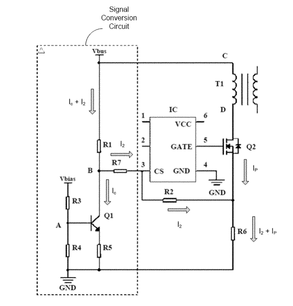
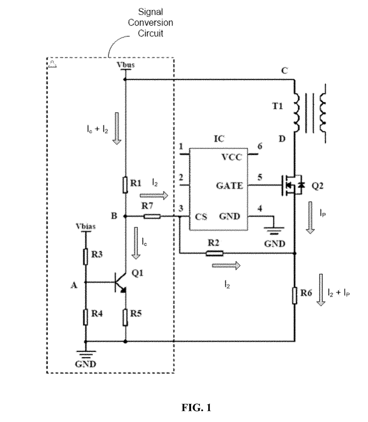
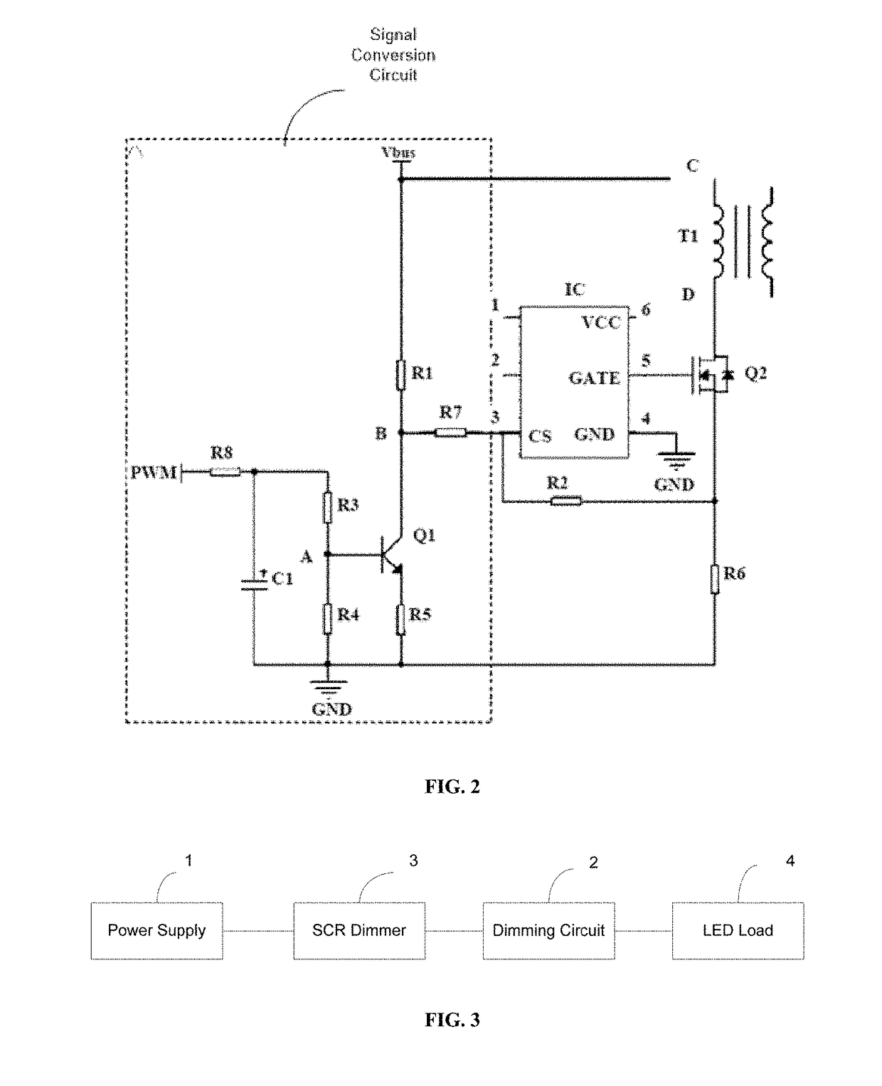
[0024]The present disclosure provides a dimming circuit and dimming system suitable for SCR dimmer. An exemplary dimmer circuit may include a signal conversion circuit and a power factor correction circuit.

[0025]The signal conversion circuit, as shown in the dashed boxes in FIG. 1 and FIG. 2, may convert the input signal to ...


PUM


Abstract

The present disclosure provides a dimming circuit for SCR dimmer (silicon-controlled rectifier) circuit. The dimming circuit includes a signal conversion circuit for converting an input signal to a sine-wave voltage signal and output the sine-wave voltage signal to a current sampling end of a power factor correction circuit. The dimming circuit also includes the power factor correction circuit to receive the sine-wave voltage signal for correcting power factor. A biasing current is generated according to the input signal and is positively correlated to the input signal, and a sine-wave current signal corresponding to the sine-wave voltage signal is a sum of the biasing current and a primary current of a transformer in the power factor correction circuit.

Description

CROSS-REFERENCES TO RELATED APPLICATIONS[0001]This PCT patent application is a national phase entry under 35 U.S.C. §371 of International Application No. PCT / CN2015 / 099584, filed on Dec. 29, 2015, which claims the priority of Chinese Patent Application No. CN201410854807.1, filed on Dec. 31, 2014, the entire contents of which are incorporated herein by reference.FIELD OF THE DISCLOSURE[0002]The present disclosure generally relates to the field of light emitting diode (LED) technologies and, more particularly, relates to a dimming circuit and dimming system suitable for a silicon-controlled rectifier (SCR) type dimmer.BACKGROUND[0003]An LED (i.e., light emitting diode) is a semiconductor device capable of converting electric energy to visible light. An LED can directly convert electricity to light. LED lighting can provide advantages including energy conservation, environmental protection, controllable lighting, strong practicability, high stability, short response time, and long ope...

Claims


Application Information

Patent Timeline
Patent Type & Authority Patents(United States)
IPC IPC(8): G05F1/00H05B37/02H05B39/04H05B41/36H05B33/08H02M1/42H02M7/155H05B44/00
CPCH05B33/0815H02M1/4208H02M7/155H05B33/0809H05B33/0845H02M2001/4283H05B45/10H05B45/382H02M1/4283
Inventor TIAN, ZHIBINLOU, JUNSHANSUN, CHAOQUNSHEN, JINXIANG
Owner SENGLED OPTOELECTRONICS
Why Eureka
Eureka Blog
Learn More