
Card with metal layer and an antenna

a metal foil/film/layer, multi-layer technology, applied in the direction of instruments, electrical/magnetic thickness measurement, radiating element structural forms, etc., can solve the problems of not being able to just make the insulator layer arbitrarily thick, not being able to meet the needs of insulator layer thickness, etc., to achieve reliable communication and enhance the transmission/reception of signals

Active Publication Date: 2017-08-01
COMPOSECURE LLC
View PDF10 Cites 43 Cited by
  • Summary
  • Abstract
  • Description
  • Claims
  • Application Information

AI Technical Summary

Benefits of technology

The invention is about improving the communication between a card and a card reader by adjusting the distance between the card's antenna and a metal layer on the card. This is done by controlling the thickness of an insulating layer between the antenna and the metal layer. The invention allows for better signal transmission and reception at specific distances and frequencies, resulting in improved performance of the card's inductive coupling system.

Problems solved by technology

However, the metal foil / film / layer presents a problem since it functions to attenuate (absorb) the signals transmitted between the card reader and the chip limiting communication or even making it impossible.
However, this is not acceptable where the permissible thickness of the insulator layer is limited.
Thus, it is not satisfactory to just make the insulator layer arbitrarily very thick since such thick layers interfere with other requirements in the manufacture of smart cards.
The problem of manufacturing a reliable smart card is even greater particularly when the card includes a metal layer which interferes with the transmission / reception of signals between the smart card and a card reader.
Thus, a significant problem faced by Applicants related to selecting the thickness of an insulator layer, extending within a prescribed range, which can provide reliable readings of card data by a card reader located at a prescribed distance and at a prescribed frequency of operation.
An associated problem was finding a thickness for the insulator layer which provided improved transmission / reception.

Method used


Image

  • Card with metal layer and an antenna
  • Card with metal layer and an antenna
  • Card with metal layer and an antenna

Examples


Embodiment Construction

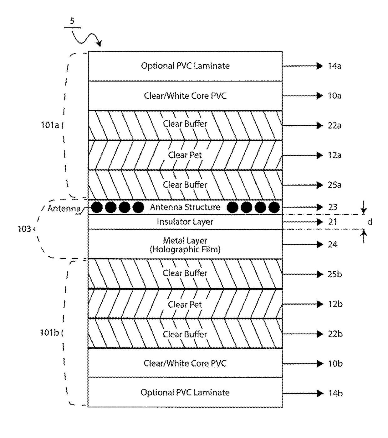
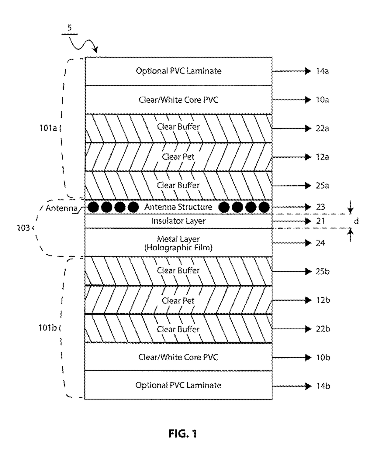
[0019]Referring to FIGS. 1 through 4 there is shown a generally symmetrical type of card structure illustrating the use of buffer layers in a card construction to absorb the difference between layers having substantially different characteristics which enables many different types of sturdy and secure cards to be manufactured. Card 5 includes (in the Figures) a top section 101a, a correspondingly symmetrically shaped bottom section 101b and a center section 103.

[0020]Top section 101a includes a PVC overlay 14a mounted over a core PVC layer 10a, overlying a buffer layer 22a, which, in turn, overlies a PET layer 12a, overlying a buffer layer 25a.

[0021]Bottom section 101b includes a PVC overlay 14b formed under a core PVC layer 10b, underlying a buffer layer 22b, which underlies a PET layer 12b, underlying a buffer layer 25b. The buffer layers reduce the stress between the very dissimilar materials enabling a more stable structure having a much greater life time and of greater sturdin...


PUM

PropertyMeasurementUnit
thicknessaaaaaaaaaa
thicknessaaaaaaaaaa
thicknessaaaaaaaaaa

Abstract

In a smart card having an antenna structure and a metal layer, an insulator layer is formed between the antenna structure and the metal layer to compensate for the attenuation due to the metal layer. The thickness of the insulator layer affects the capacitive coupling between the antenna structure and the metal layer and is selected to have a value which optimizes the transmission / reception of signals between the card and a card reader.

Description

[0001]This application claims priority based on a provisional application titled COMPOSITE CARD WITH HOLOGRAPHIC METAL FOIL AND AN INDUCTIVE COUPLING ANTENNA bearing Ser. No. 61 / 962,873 filed Nov. 18, 2013 whose teachings are incorporated herein by reference.BACKGROUND OF THE INVENTION[0002]This invention relates to smart cards and in particular to multi layered smart cards having a metal foil / film / layer and an antenna structure for receiving or transmitting signals between the smart cards and a card reader.[0003]As shown in FIGS. 1, 2(a), 2(b) and 2C a typical smart card includes an antenna structure coupled (directly or electromagnetically) to a microprocessor or microcomputer (also referred to as a “chip”) also located on or within the card. The antenna structure functions to enable contactless communication between a card reader (also referred to as a “transponder” or “transceiver”) and the microprocessor. That is: (a) signals emitted by the card reader are electromagnetically c...

Claims


Application Information

Patent Timeline
Patent Type & Authority Patents(United States)
IPC IPC(8): G06K19/02H01Q7/00G06K19/06G06K19/077G01B7/06H01Q1/38H01Q1/22
CPCG06K19/07722G01B7/06G06K19/07783H01Q1/2225H01Q1/38H01Q7/00Y10T29/49016
Inventor HERSLOW, JOHNLOGAN, MICHELEFINN, DAVID
Owner COMPOSECURE LLC
Learn More