Sample holder and charged particle device

a technology of charged particles and sample holders, which is applied in the direction of material analysis using wave/particle radiation, instruments, electrochemical generators, etc., can solve the problem of large limit on the maintenance of pressure in the vicinity of samples at the actual operational environment, and achieve the effects of reducing working time, rapid advancement of research, and reducing the degradation process

Active Publication Date: 2017-08-01
HITACHI HIGH-TECH CORP
View PDF16 Cites 3 Cited by
  • Summary
  • Abstract
  • Description
  • Claims
  • Application Information

AI Technical Summary

Benefits of technology

[0014]With the present invention, it is possible to observe dynamic change using secondary electrons while controlling the pressure in the vicinity of a desired sample. Further, since it is possible to perform observation while heating the sample, the invention greatly contributes to research of degradation process in the field of fuel cell. Further, it is possible to load, in addition to a powder sample, a micro sample formed with the charged particle device e.g. a focused ion beam processing observation device, in the sample holder according to the present invention. Accordingly, it is possible to greatly reduce working time from process to observation by enabling all the series of work steps from process to observation with one holder, which contributes to rapid advancement of researches in various fields.

Problems solved by technology

There is a large limit on maintenance of the pressure in the vicinity of the sample at the actual operational environment, i.e. so-called atmospheric pressure.

Method used


Image

  • Sample holder and charged particle device
  • Sample holder and charged particle device
  • Sample holder and charged particle device

Examples


first embodiment

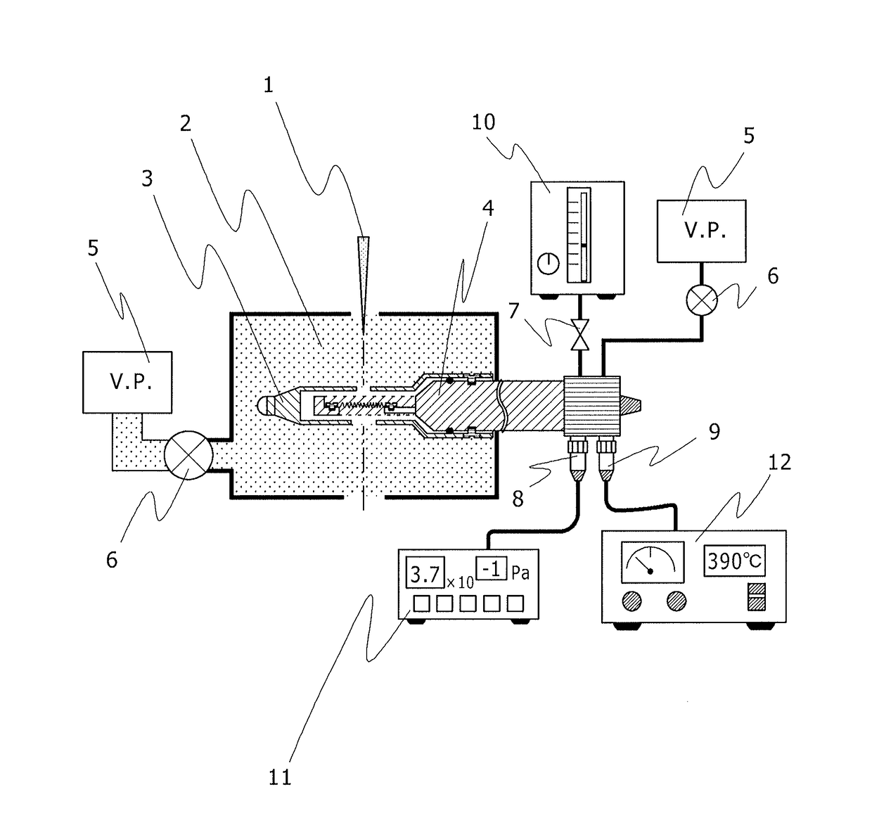
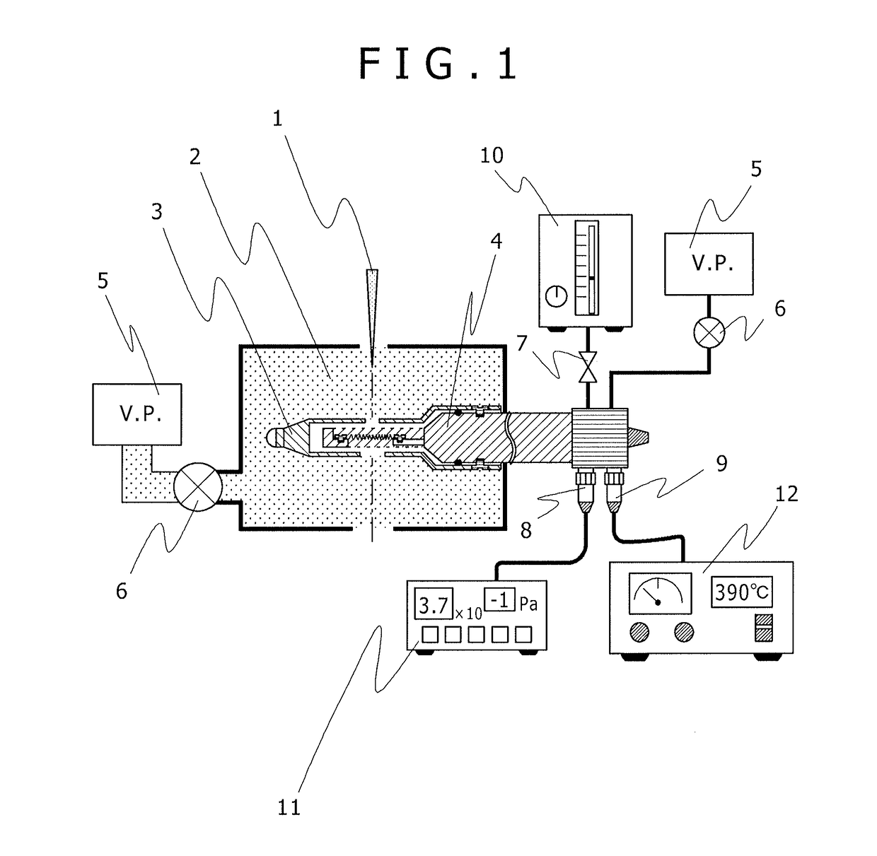
[0032]FIG. 3 shows an embodiment of the present invention, and shows the tip of the sample holder 4 described in FIG. 1 in detail. As in the case of FIG. 2, the sample holder 4 is provided with the O-ring 21 to atmospherically block only the surrounding of the sample 20 with the sample holder tip cap 3. Further, it has the sample holder tip cap fixing screw 22 to fix the sample holder tip cap 3. In the sample holder tip cap 3, the charged particle passage hole (micro orifice) 18 through which the charged particles A1 pass is provided in the positions above and below the sample 20. The charged particle passage hole (micro orifice) 18 above the sample 20 has a hole diameter to pass the secondary electrons 15 emanated from the sample 20. It is possible to enable image observation with the image display unit 14 via the secondary electron detector 13. Further, in addition to the charged particle passage and gas exhaust hole 19 below the sample 20, a structure to positively perform differ...

second embodiment

[0033]FIG. 4 shows an embodiment of the present invention and is a detailed diagram of the tip of the sample holder 4. The sample holder 4 is provided with the heater 16 for loading the sample 20, and the sample 20 is loaded there. Further, it has a structure provided with the gas introduction pipe 26 and the gas exhaust pipe 25 directed to the sample 20, and has a minute pressure measuring element 24 to detect the pressure in the vicinity of the sample 20.

third embodiment

[0034]FIG. 6 shows an embodiment of the present invention and shows the tip of the sample holder 4 described in FIG. 5 in detail.


PUM

PropertyMeasurementUnit
atmospheric pressureaaaaaaaaaa
diameteraaaaaaaaaa
hole diametersaaaaaaaaaa

Abstract

The objective of the present invention is to maintain the surrounding of a sample at atmospheric pressure and efficiently detect secondary electrons. In a sample chamber of a charged particle device, a sample holder (4) has: a gas introduction pipe and a gas evacuation pipe for controlling the vicinity of a sample (20) to be an atmospheric pressure environment; a charged particle passage hole (18) and a micro-orifice (18) enabling detection of secondary electrons (15) emitted from the sample (20), co-located above the sample (20); and a charged particle passage hole (19) with a hole diameter larger than the micro-orifice (18) above the sample (20) so as to be capable of actively evacuating gas during gas introduction.

Description

TECHNICAL FIELD[0001]The present invention relates to an environmental control charged particle observation system. The system is used, in observation of a sample with a charged particle device e.g. an electron microscope, for efficiently detecting secondary electrons generated from the sample and performing efficient heating-observation on the sample while controlling the pressure in the vicinity of the sample. Accordingly, in analysis of degradation process in a recent fuel cell or the like, it is greatly useful for observation of dynamic change of the structure upon gas introduction and heating, by coordinating the observation environment of the electron microscope with actual operational environment.BACKGROUND ART[0002]In a charged particle device e.g. an electron microscope, in observation of a sample using a transmission electron image or a secondary electron image, in the field of electron microscope, observation is basically performed in a state where high-vacuum environment...

Claims


Application Information

Patent Timeline
Patent Type & Authority Patents(United States)
IPC IPC(8): H01J37/00H01J37/18H01J37/20H01J37/285G01N23/22H01M8/04664
CPCH01J37/20G01N23/22H01J37/18H01J37/285H01J2237/006H01J2237/188H01J2237/2003H01J2237/2802H01J2237/2806H01M8/04671G01N23/2204Y02E60/50
Inventor NAGAKUBO, YASUHIRANAGAOKI, ISAOMATSUMOTO, HIROAKISATO, TAKESHI
Owner HITACHI HIGH-TECH CORP
Why Eureka
Try Eureka