
Resistance band assembly and a method of varying a resistive force applied thereby

a resistance band and resistance technology, applied in the field of resistance band assembly and a resistance band variation method, can solve the problems of inability to adjust, inexperienced users or too ambitious people may inadvertently injure themselves, discourage people from undertaking a full exercise routine, etc., to achieve easy adjustment, and increase the intensity of the workout

Active Publication Date: 2017-08-08
KAYEZEN LLC
View PDF173 Cites 14 Cited by
  • Summary
  • Abstract
  • Description
  • Claims
  • Application Information

AI Technical Summary

Benefits of technology

[0011]There is still a need in the art for an improved system which helps a user to exercise a number of different parts of the body effectively and which uses resistance bands instead of weights as a way to increase the intensity of the workout as the user gets fitter.
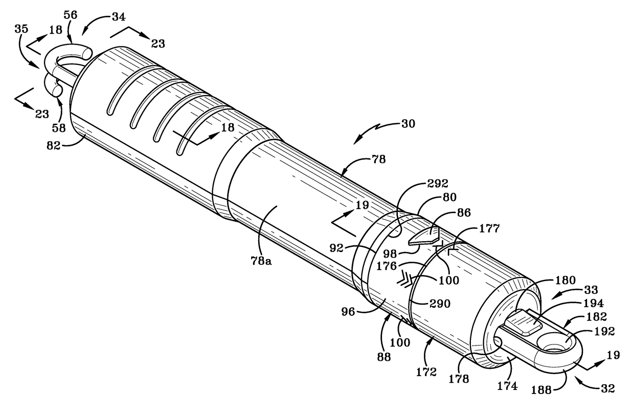
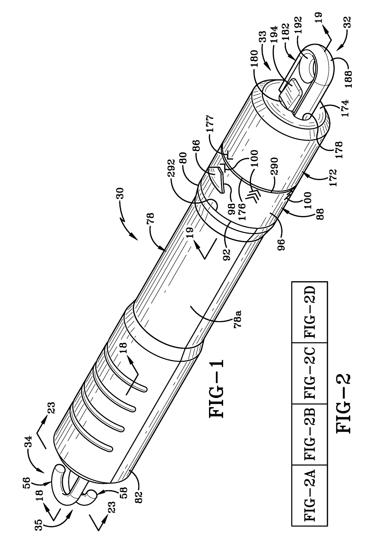
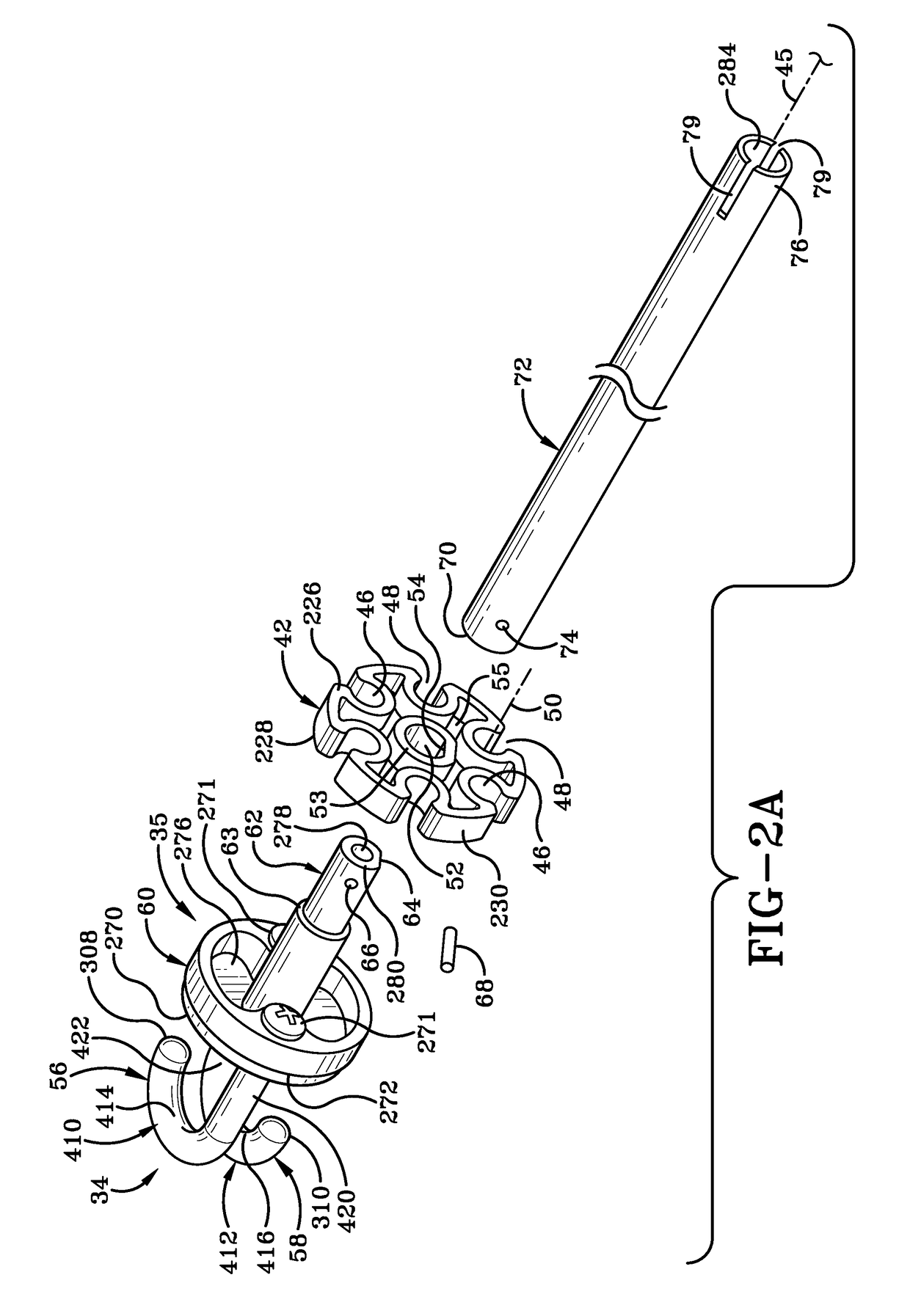
[0012]The system disclosed herein includes a fitness station which may act as an anchor and an improved resistance band assembly for use with the fitness station. The system may be used in a gym or in an outdoor fitness area and the resistance band assembly is readily adjustable to change the resistance provided by the assembly. A user may therefore readily exercise their whole body and the system provides a way for progressively increasing the intensity of the workout.
[0014]The fitness station includes a base; a support extending upwardly from the base; a first arm extending outwardly from the support a distance vertically above the base; and a plurality of attachment members provided on one or more of the base, the support or the first arm. The resistance band assembly is selectively engageable with one of the attachment members and is operable to apply a resistive force during a performance of an exercise. The resistance band assembly includes a housing that is at least partially rigid and at least a first resilient member for providing the resistive force provided within the housing. The resistance band assembly is such that a user is able to grasp the housing thereof in a single hand and readily attach the assembly to the fitness station; even to attachment members on the fitness station that are located a distance above the user's head. The rigidity of the housing helps ensure that this easy engagement of the assembly to the fitness station is possible.

Problems solved by technology

If the user is inexperienced, there is the tendency to avoid particular machines simply because it is difficult to figure out what one is supposed to do on that machine.
An inexperienced user or someone who is too ambitious may inadvertently injure themselves if too much weight is applied to any particular exercise.
Additionally, in busier gyms, the wait time for particular machines may be long enough that it tends to discourage people from undertaking a full exercise routine.
Unlike gyms, these locations have fewer pieces of equipment for the user to use and most often there is no way to increase the intensity of the workout as the user gets fitter.
Repeatedly having to swap out the resistance band for different exercises can be frustrating and time-consuming.

Method used


Image

  • Resistance band assembly and a method of varying a resistive force applied thereby
  • Resistance band assembly and a method of varying a resistive force applied thereby
  • Resistance band assembly and a method of varying a resistive force applied thereby

Examples


first embodiment

[0240]Fifth arm 523 is a generally U-shaped member that is mounted on exterior surface 538b of support member 538 by way of a mounting bracket 596. fifth arm 523 is shown in FIG. 40. Fifth arm 523 may be mounted on support member 538 at a level that is aligned with approximately midway along length of first slot 544. Bracket 596 secures fifth arm 523 to support 514 in a fixed and unchangeable orientation. Fifth arm 523 may be oriented so that it is substantially horizontally mounted and is generally parallel to upper surfaces 524a, 526a of first and second base members 524, 526. A cushioning grip 598 is provided on each end of fifth arm 523. Fifth arm 523 may be used as a dip bar for performing triceps dips or other similar exercises.

second embodiment

[0241]FIG. 43 shows the first arm, generally indicated at 616. First arm 616 may be adjustably mounted to support 514. In particular, the distance between first arm 616 and base 512 is selectively variable by moving first arm 616 toward or away from base 512. First arm 616, like first arm 516, is generally U-shaped when viewed from above and comprises a first section 616a and a second section 616b. First and second sections 616a, 616b are substantially identical to each other and are mounted in such a manner that they are mirror images of each other relative to support member 538. Each of the first and second sections 616a, 616b is generally L-shaped and comprises a generally laterally extending first arm portion 656 and a forward extending second arm portion (not shown in FIG. 43 but substantially identical to second arm portion 558). First and second sections 616a, 616b may be generally circular in cross section.

[0242]A clamping assembly 660 secures each first arm 656 to support m...

third embodiment

[0250]FIG. 44 also shows the first arm, generally indicated in this figure at 716. First arm 716 includes additional attachment members 778 which may be provided at intervals on one or more of bottom, top, and rear surfaces of first arm 716 as well as on the front surface thereof.

[0251]In accordance with another aspect of the invention and as shown in FIG. 44, attachment members 801 may also be provided on upper and / or lower surfaces of shaft 800 of fifth arm 723. Some type of resistance band (not shown in these figures) may be engaged between any selected attachment member 801 on fifth arm 723 and any selected attachment member 778 of first arm 716 to increase the resistance to the pivotal motion of fifth arm 723 as indicated by arrow “K”. This increased resistance may be desirable as a user gets fitter and stronger.

[0252]It will be understood that substantially all of the first, third, fourth, and fifth attachment members are illustrated herein as being spaced at regular intervals...


PUM


Abstract

A method of varying a resistive force applied by exercise equipment including providing a resistance band assembly for providing resistive force during the performance of an exercise. The resistance band assembly includes a housing having a first end, a second end, and a longitudinal axis extending therebetween. A bore is defined in the housing and a connector is provided in the bore. The connector includes first and second surfaces and a hole is defined in the connector and extends between the surfaces. A disc is also provided in the bore and also has a first and second surface. An aperture is defined in the disc and extends between the first and second surfaces thereof. A first and second resilient member is provided and these resilient members are selectively engageable with the resistance band assembly to provide a first resistive force during the performance of an exercise.

Description

CROSS REFERENCE TO RELATED APPLICATIONS[0001]This application is a Continuation-in-Part of U.S. patent application Ser. No. 13 / 836,359, filed Mar. 15, 2013, the entire specification of which is incorporated herein by reference. This application also claims the benefit of U.S. Provisional Application Ser. No. 61 / 931,842 filed on Jan. 27, 2014; U.S. Provisional Application Ser. No. 61 / 931,887 filed on Jan. 27, 2014, and of U.S. Provisional Application Ser. No. 61 / 938,331 filed on Feb. 11, 2014, the entire specifications of which are incorporated herein by reference.BACKGROUND OF THE INVENTION[0002]Technical Field[0003]This invention relates generally to exercise equipment. More particularly, this invention is directed to customizable and ergonomically designed exercise equipment used for strength training and stretching. Most specifically, this invention is directed to a fitness station that may be installed in a commercial gym, a home gym, or in an outdoor exercise area and a detacha...

Claims


Application Information

Patent Timeline
Patent Type & Authority Patents(United States)
IPC IPC(8): A63B21/04A63B23/035A63B21/055A63B23/12A63B21/00A63B23/00
CPCA63B21/055A63B21/00065A63B21/00069A63B21/0442A63B21/0555A63B21/4035A63B21/4043A63B23/03508A63B23/03541A63B23/1209A63B23/1218A63B21/0557A63B2023/006
Inventor KAYE, ERIC A.CESARONI, WILLIAM C.GHASSEMIAN, MORADMATHEWS, BRIAN W.DIMONTE, EUGENE L.ZIELKE, DONOVAN D.LENZ, STEVEN M.
Owner KAYEZEN LLC
Learn More