Rotary-oscillating subassembly and rotary-oscillating volumetric pumping device for volumetrically pumping a fluid

a technology of volumetric pumping and sub-assembly, which is applied in the direction of pumps, mechanical apparatus, liquid fuel engines, etc., can solve the problems of bulky and voluminous peristaltic pumps, laborious operation, and low fluid-flow and energy efficiency, and achieve good fluid-flow and energy efficiency, and the effect of manufacturing cos

Active Publication Date: 2017-08-08
EVEON
View PDF14 Cites 9 Cited by
  • Summary
  • Abstract
  • Description
  • Claims
  • Application Information

AI Technical Summary

Benefits of technology

[0011]The object of the invention is to remedy those drawbacks by proposing a rotary-oscillating sub-assembly for positive displacement pumping and a rotary-oscillating positive displacement pumping device of manufacturing cost that is moderate, with a limited number of parts, that is reversible, that is accurate, that makes it possible to transfer viscous liquid even at high pressure, and that have a good fluid-flow and energy efficiency.
[0015]The basic idea of the invention is to provide a sealing gasket between the piston and the body, the sealing gasket having a particular shape that makes it possible to guarantee effective, sealing while limiting friction, so as to improve the energy efficiency and increase the flowrate accuracy of the rotary-oscillating sub-assembly.

Problems solved by technology

Filling is usually performed manually, and this operation is laborious, particularly since it requires specific precautions to be complied with in order to guarantee the integrity of the liquid and the safety of personnel.
The presence of silicone in direct contact with the fluid generates problems of stability for molecules while they are being stored in the cartridge prior to being used.
Peristaltic pumps are bulky and voluminous.
As a result of the flexibility of the hose, the volumetric efficiency (ratio of real flowrate divided by demanded flowrate) varies greatly with varying fluid outlet pressure, and quickly degrades metering accuracy without the help of an auxiliary sensor (e.g. a flowrate sensor).
Thus, the working pressures of such peristaltic pumps are typically lower than 5 bars, thereby limiting their use with viscous liquids.
Furthermore, that type of pump often generates miniscule bubbles of air in the fluid, which bubbles can have an unacceptable effect.
Finally, the rapid aging of the mechanical properties of the hose poses problems of changes over time in the performance and / or the reliability of that type of pump.
The same types of drawback are encountered with diaphragm pumps.
Also, check-valve pumps do not offer the possibility of having a neutral position in which all fluid flow is prevented.
Finally, they are not reversible.
However, those types of pump present poor self-priming capacity and they retain large internal volumes of fluid, making them difficult to use for such medical, cosmetic, or veterinary applications.
However, proper operation of the rotary-oscillating positive displacement pumping device requires good sealing between the piston and the cavity, and this requires tight manufacturing tolerances that are difficult to comply with without considerable production costs and / or significant friction that penalizes the energy efficiency of the rotary-oscillating positive displacement pumping device.

Method used


Image

  • Rotary-oscillating subassembly and rotary-oscillating volumetric pumping device for volumetrically pumping a fluid
  • Rotary-oscillating subassembly and rotary-oscillating volumetric pumping device for volumetrically pumping a fluid
  • Rotary-oscillating subassembly and rotary-oscillating volumetric pumping device for volumetrically pumping a fluid

Examples


first embodiment

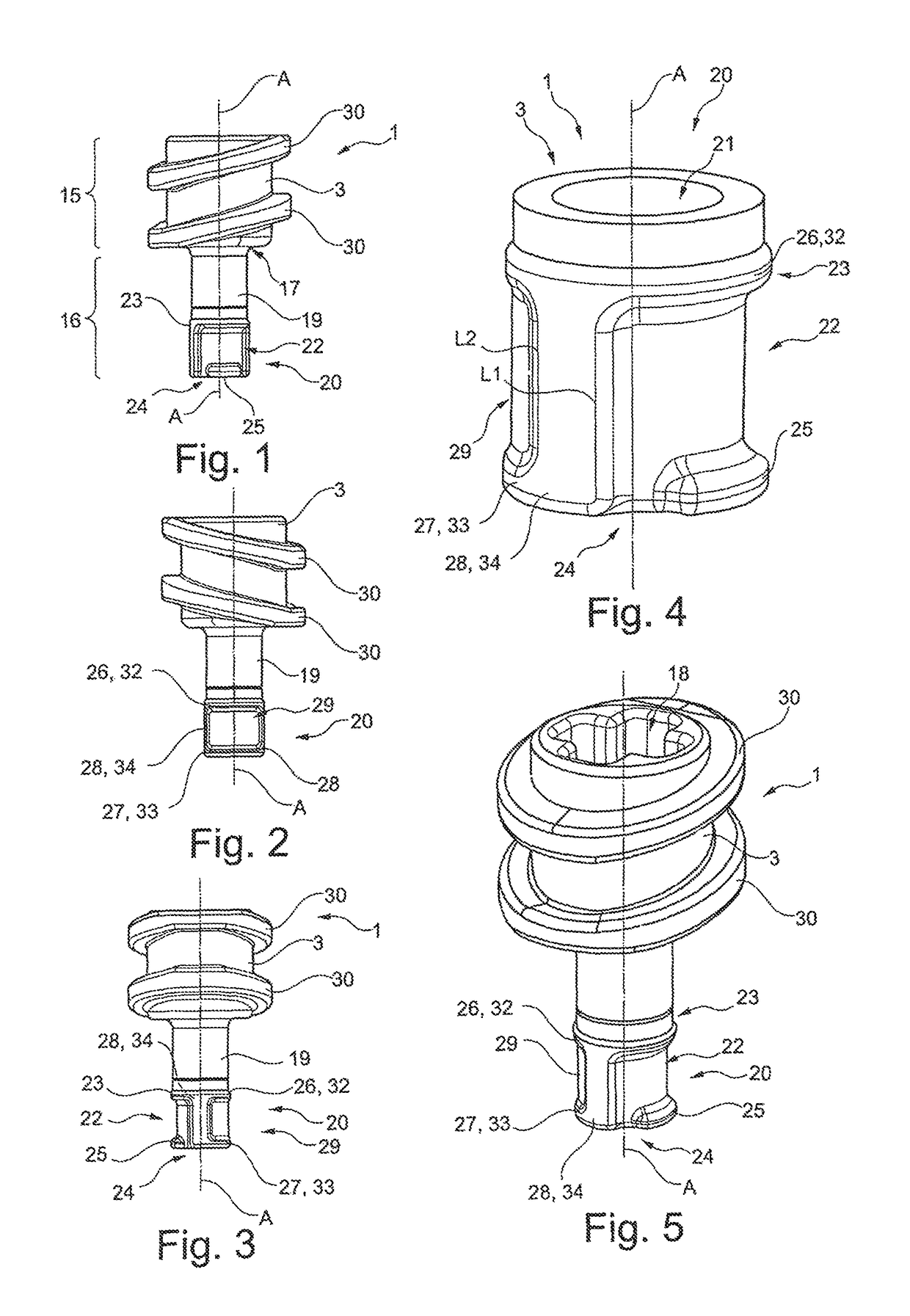
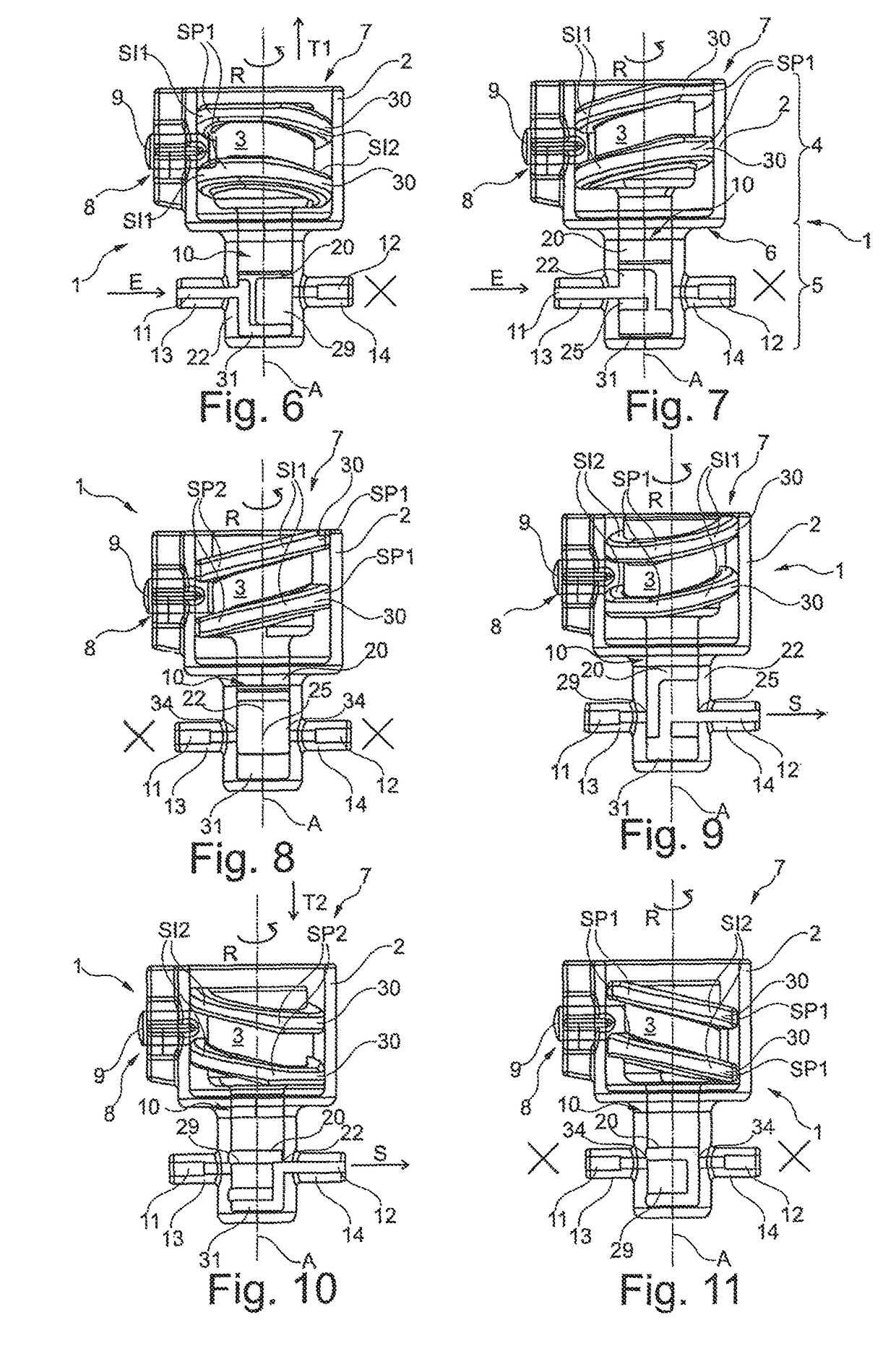
[0045]With reference to FIGS. 6 to 11, the rotary-oscillating sub-assembly 1 in the invention comprises a body 2 and a piston 3.

[0046]As shown in detail in FIG. 7, the body 2 is hollow and is formed of two cylindrical portions 4, 5 of different diameters, connected together via a shoulder 6. By way of example, the body 2 is made of plastics material or of any other suitable material.

[0047]The inside of the larger-diameter cylindrical portion 4 forms a bore 7 of longitudinal axis A. The free end of the larger-diameter cylindrical portion 4 is open and is for receiving the piston 3 in longitudinal sliding. The other end is connected to the smaller-diameter cylindrical portion 5 via the shoulder 6. The wall of the larger-diameter cylindrical portion 4 has an orifice 8 passing therethrough for receiving a radial guide finger 9 that is arranged so as to extend into the bore 7. In the embodiment shown, the guide finger 9 is a pin. The guide finger 9 may also be secured to the body by adhe...

second embodiment

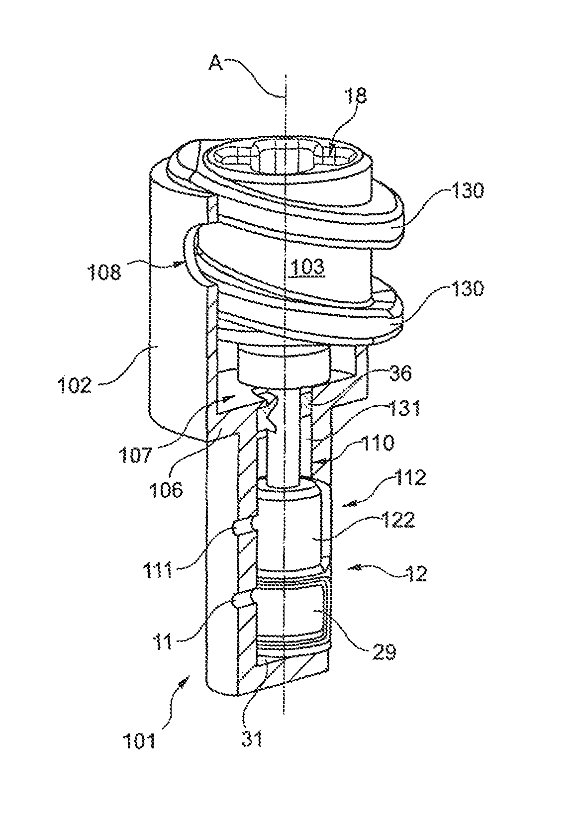
[0080]The rotary-oscillating sub-assembly 101 in the invention is shown in FIGS. 13 to 20 and presents a double-acting configuration. To this end, it comprises two stages, a first stage similar to the stage of the rotary-oscillating sub-assembly 1, and a second stage comprising two ducts 111, 112, a working chamber 131, a channel 122, a recessed zone 129 like those of the first stage. Thus, a single channel 22, 122 corresponds to each pair of “intake” and “discharge” ducts 11, 12.

[0081]In the embodiment shown, the “intake” ducts 11, 111 are superposed longitudinally, the “discharge” ducts 12, 112 are superposed longitudinally, the channels 22, 122 are situated at 180° from each other, and the recessed zones 29, 129 are situated at 180° from each other. The fluid-flow connections via the “intake” ducts 11, 111 and the “discharge” ducts 12, 112 are at 180°. The body 102 includes a cavity 110 that presents a greater height longitudinally, thus making it possible to house both stages. T...


PUM


Abstract

A rotary oscillating sub-assembly for positive displacement pumping of a fluid, said sub-assembly comprising: a hollow body defining a cavity having a wall with two ducts passing therethrough; a piston co-operating with said cavity to define a working chamber and including a channel that opens out longitudinally into said working chamber, said piston being movable angularly so as to put said working chamber into fluid-flow communication with one, then none, then the other of said ducts, and being movable in longitudinal translation to reciprocate so as to cause the volume of said working chamber to vary and successively suck in and then discharge said fluid, said piston carrying a sealing gasket that is formed of at least a sealing ring, a sealing half-ring, and at least one sealing strip that longitudinally connects said sealing ring to said sealing half-ring.

Description

CROSS REFERENCE TO RELATED APPLICATIONS[0001]This application is the U.S. National Stage of International Application Number PCT / FR2014 / 051869 filed on Jul. 21, 2014, which application claims priority under 35 USC §119 to French Patent Application No. 1357185 filed on Jul. 22, 2013. Both applications are hereby incorporated by reference in their entirety.TECHNICAL FIELD[0002]The invention generally relates to a rotary-oscillating sub-assembly and to a rotary-oscillating pumping device for positive displacement pumping of a fluid.Background of the Invention[0003]The use of positive displacement pumping devices is known for producing and / or reconstituting mixtures (liquid-solid or liquid-liquid mixtures) and / or administering fluids (by injection, infusion, orally, spray, ...), in particular for medical, cosmetic, veterinary applications. For these types of applications, accurate quantities of fluid need to be pumped in a controlled manner, e.g. towards a container, or in order to admi...

Claims


Application Information

Patent Timeline
Patent Type & Authority Patents(United States)
IPC IPC(8): F04B7/00F04B9/04F04B7/06F04B53/02F04B53/14F04C2/00F04B7/04F04C13/00F04C9/00F04C15/06F04C15/00F04B19/22
CPCF04C13/001F04B7/04F04B7/06F04B9/047F04B53/02F04B53/143F04C2/00F04C9/007F04C15/0003F04C15/0057F04C15/064F04B19/22
Inventor WATTELLIER, ARNAUDDEHAN, CHRISTOPHE
Owner EVEON
Why Eureka
Try Eureka