
Route planner for transportation systems

a transportation system and route planner technology, applied in the field of computer systems, can solve the problems of insufficient real-world return of static route planners, insufficient accuracy of bus arrival times, and high stochastic and time-dependent travel time in urban traffic environments

Active Publication Date: 2017-08-08
SAP AG
View PDF4 Cites 8 Cited by
  • Summary
  • Abstract
  • Description
  • Claims
  • Application Information

AI Technical Summary

Benefits of technology

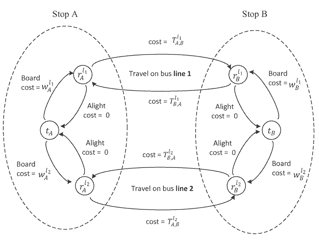
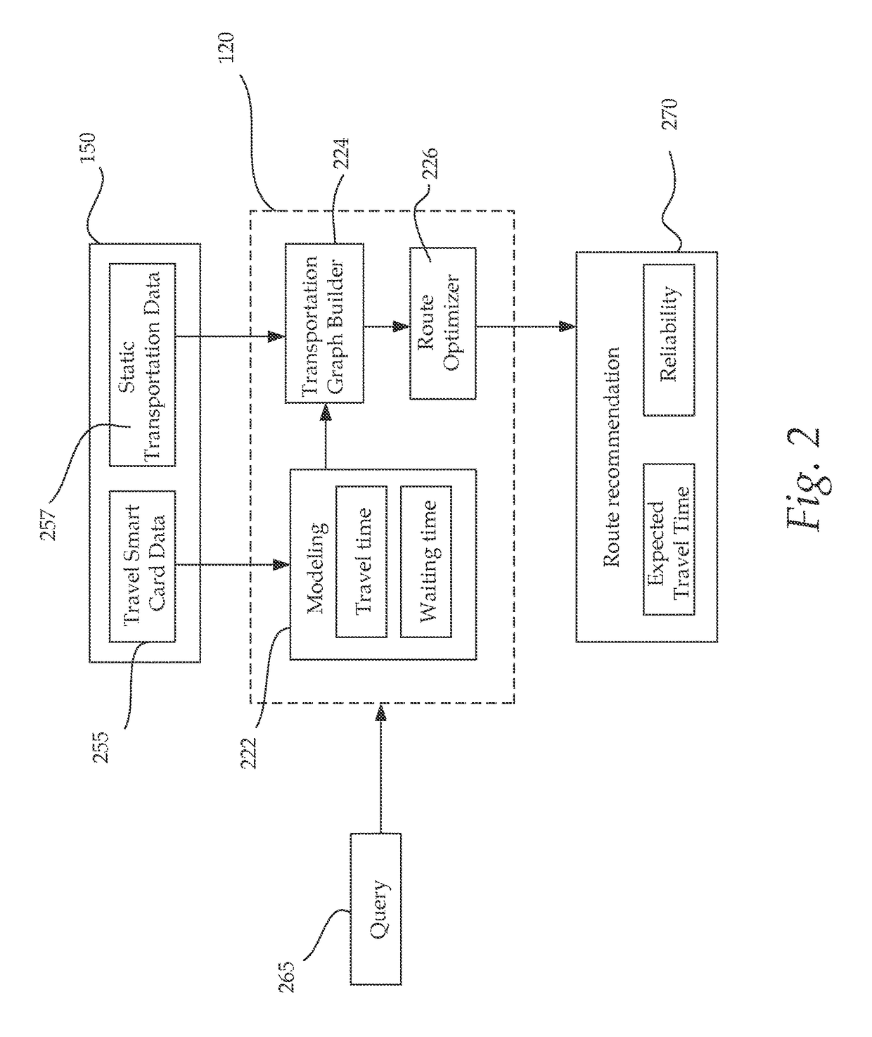
The patent text describes a computer system for planning transportation routes based on a stochastic time-dependent framework. The system takes into account factors like traffic and weather to determine the best route for a commuter in a transit network. Traditional route planners use a fixed schedule and are inadequate for real-world traffic situations. The present system uses continuous distributions of travel time and waiting time data from commuters to generate a transportation graph with nodes and edges, and calculates the expected costs of routes based on the costs of the edges in the transportation graph. The system provides accurate costs and recommendations for routes based on the user's query. The technical effect of this patent is to provide a more efficient and effective tool for planning transportation routes in urban environments, considering real-time traffic and weather conditions.

Problems solved by technology

However, in a realistic transit network, buses' arrival times are not as accurate as scheduled since they are largely dependent on real-time traffic situations.
In fact, the travel time in an urban traffic environment is highly stochastic and time-dependent.
Hence, the results returned by static route planners are often inadequate in real world and cause user dissatisfaction.
Additionally, existing route planners have several drawbacks.
Next, the travel time estimated by the route planners is not accurate.

Method used


Image

  • Route planner for transportation systems
  • Route planner for transportation systems
  • Route planner for transportation systems

Examples


Embodiment Construction

[0022]In the following description, for purposes of explanation, specific numbers, materials and configurations are set forth in order to provide a thorough understanding of the present frameworks and methods and in order to meet statutory written description, enablement, and best-mode requirements. However, it will be apparent to one skilled in the art that the present frameworks and methods may be practiced without the specific exemplary details. In other instances, well-known features are omitted or simplified to clarify the description of the exemplary implementations of the present framework and methods, and to thereby better explain the present framework and methods. Furthermore, for ease of understanding, certain method steps are delineated as separate steps; however, these separately delineated steps should not be construed as necessarily order dependent in their performance.

[0023]A framework for a dynamic route planning system which recommends optimal route in a stochastic ...


PUM


Abstract

A computer-implemented technology for planning routes is described herein. In accordance with one aspect, travel data of commuters of a transportation network are provided. Continuous distributions of travel time and waiting time are generated from the travel data. The continuous distributions of travel time and waiting time are associated to a transportation graph of the transportation network. The transportation graph includes nodes corresponding to stops of the transportation network and edges interconnecting the nodes. Travel time and waiting time are associated as costs of the edges in the transportation graph. In response to receiving input parameters, expected costs of candidate routes in the transportation graph are determined in accordance with a modified multi criteria shortest path technique. The modified multi criteria shortest path technique invokes a subroutine to retrieve accurate costs of routes based at least on the costs of the edges in the transportation graph. Route recommendations are provided based on the expected costs of the candidate routes.

Description

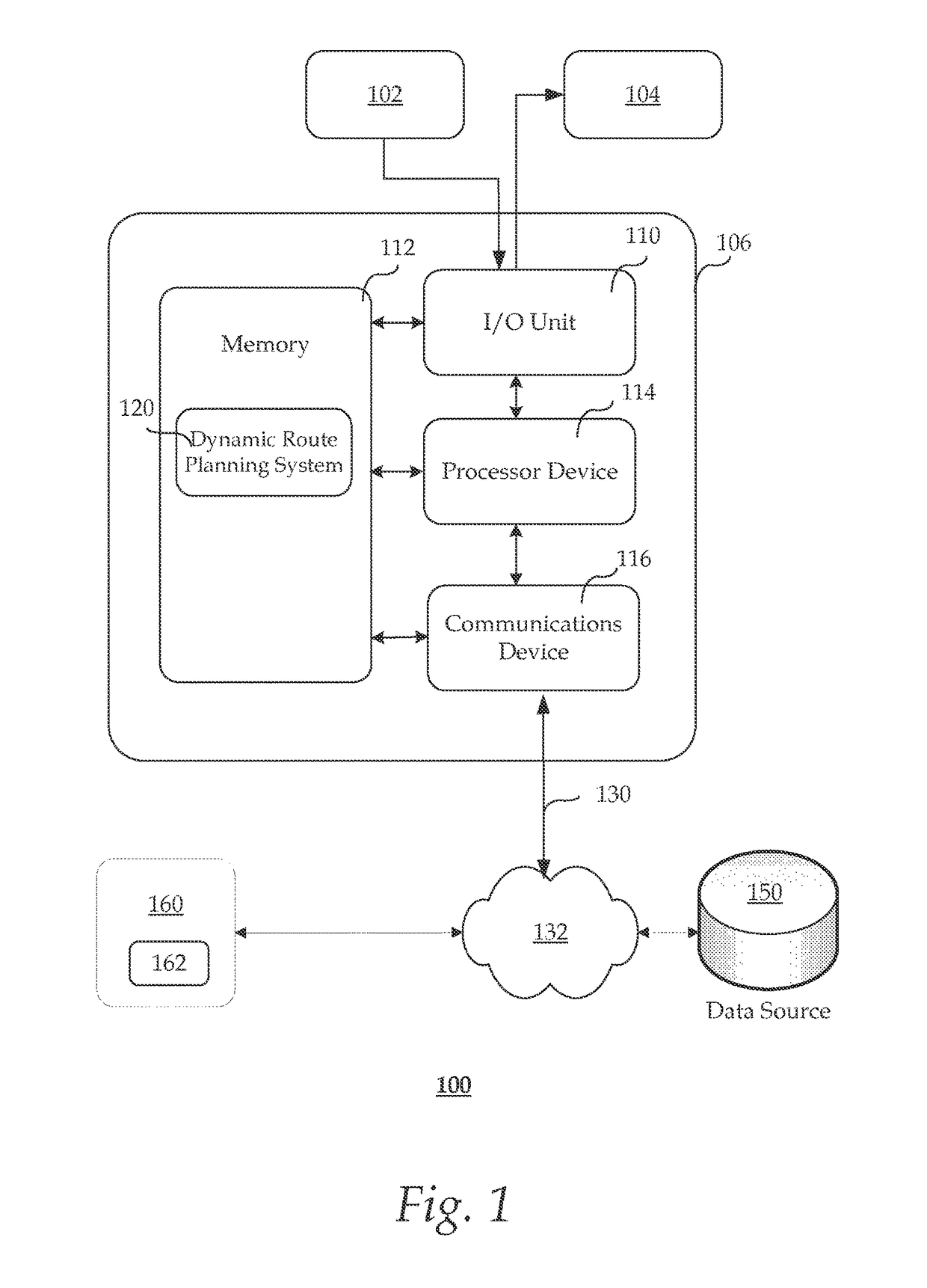
CROSS-REFERENCE TO RELATED APPLICATIONS[0001]This application cross-references to U.S. patent application Ser. No. 14 / 840,069, titled “DIVERSIFIED ROUTE PLANNING FOR PUBLIC TRANSPORTATION NETWORK” that is concurrently filed and assigned to the same assignee as this application, which is herein incorporated by reference for all purposes.TECHNICAL FIELD[0002]The present disclosure relates to computer systems, and more specifically, to a system for planning transportation routes based on a stochastic time-dependent framework.BACKGROUND[0003]Intelligent urban transportation systems are becoming increasingly important for commuters in cities. Such systems, for example, enable city-dwellers to quickly identify an optimal route in a transit network between a specified origin and destination when planning trips. In many aspects, route planning is an important part of intelligent transportation systems.[0004]Traditional route planners of public transportation such as buses follow a fixed or ...

Claims


Application Information

Patent Timeline
IPC IPC(8): G01C21/20G01C21/34G08G1/01
CPCG01C21/20G01C21/3446G01C21/3453G08G1/0125G06Q10/04
Inventor NI, PENGVO, HOANG TAMDAHLMEIER, DANIEL HERMANN RICHARDCAI, WENTONG
Owner SAP AG
Learn More