
Bio-medical electrode pad

a bio-medical and electrode pad technology, applied in the field of bio-medical electrode pads, can solve the problems of rigid electrode terminals and not optimally suited for directly touching biological objects, and achieve the effect of maximum flexibility of electrode arrangemen

Active Publication Date: 2017-08-15
KONINKLJIJKE PHILIPS NV
View PDF13 Cites 3 Cited by
  • Summary
  • Abstract
  • Description
  • Claims
  • Application Information

AI Technical Summary

Benefits of technology

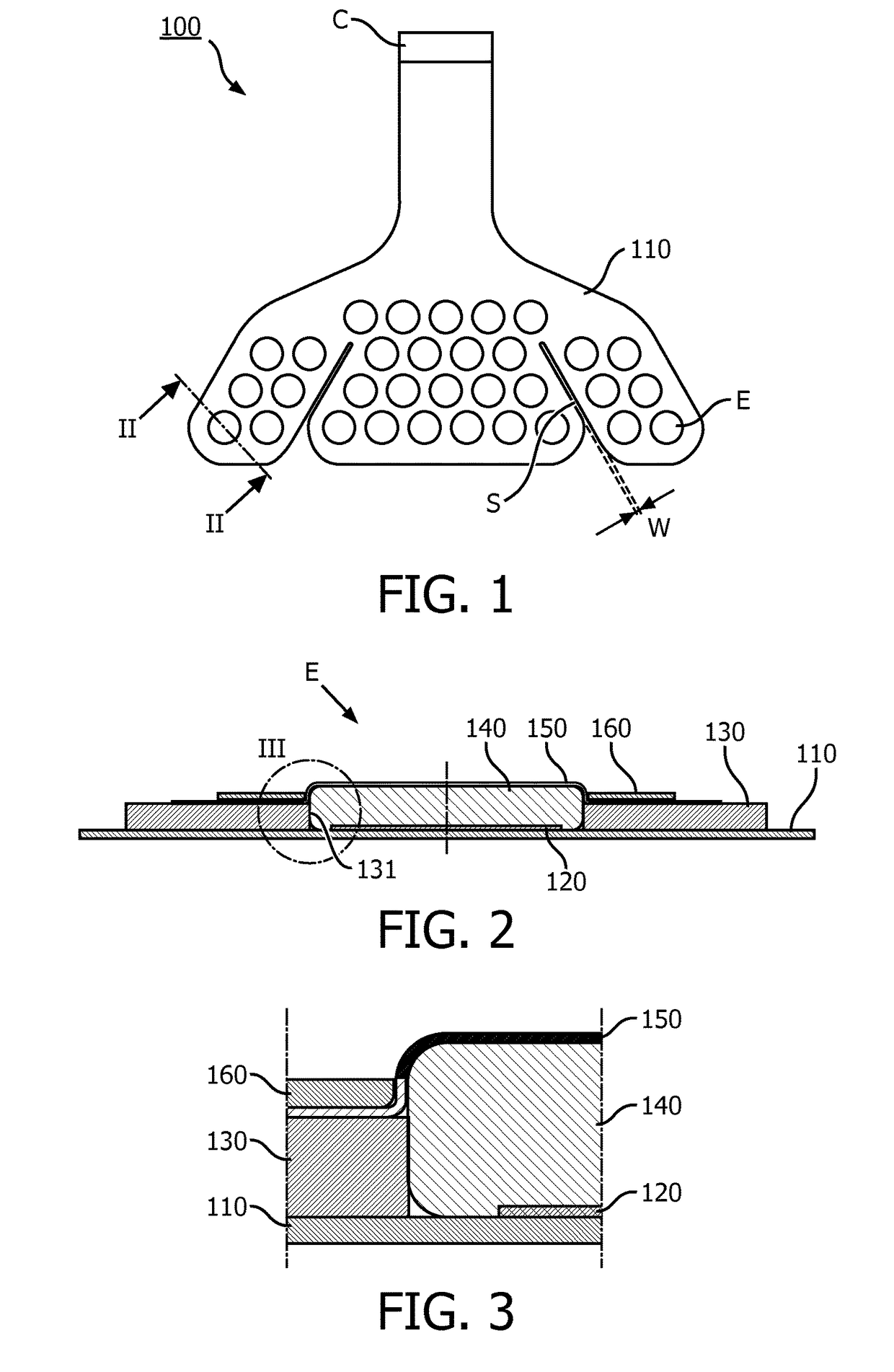
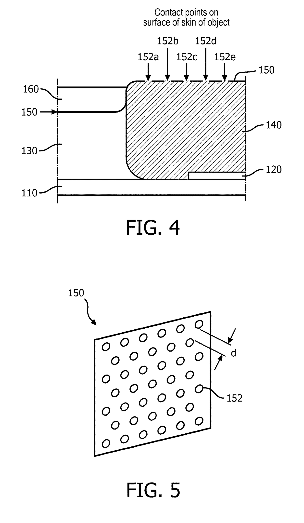
[0021]The above defined embodiments of the invention have the advantage that they allow for making a good mechanical and electrical contact to a biological object because the contact member serves as an interface between said object and the electrode terminal. Moreover, long-term functioning of this design is guaranteed by the usage of the retainer mesh that covers the contact member. The retainer mesh provides a proper attachment of the contact member to the electrode terminal and prevents sticking of the contact member to the biological object (during usage) and thus avoiding annoyance and also ease the application and removal on human or animal (biological object) that are often painful, while at the same time allowing electrical contact between the contact member and the biological object directly through a plurality of openings, also may be referred to as the mesh openings.
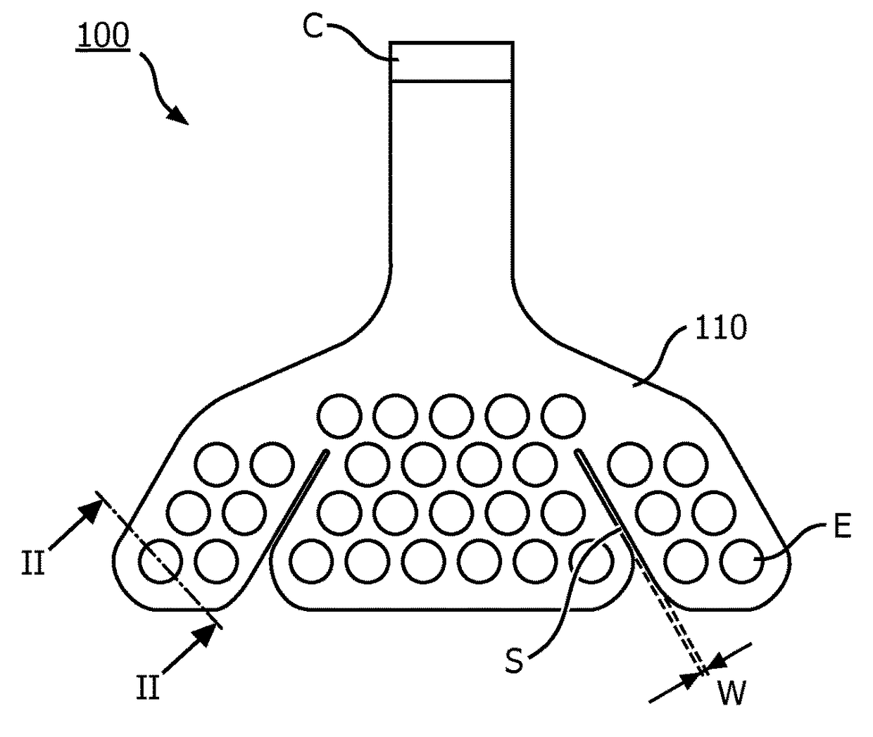
[0046]The slit may completely lie in the interior of the carrier. In a preferred embodiment, the slit starts (or ends) however at the border of the carrier, thus allowing for a maximal flexibility of the electrode arrangement.

Problems solved by technology

The electrode terminal is typically rigid and not optimally suited for directly contacting a biological object.

Method used


Image

  • Bio-medical electrode pad
  • Bio-medical electrode pad
  • Bio-medical electrode pad

Examples


second embodiment

[0096]FIG. 8 shows an electrode pad 200. In this pad, the carrier 210 with the array of electrodes E is structured by three symmetrically arranged slits S. Moreover, the interspace distance D between two neighboring electrodes that are not separated by a slit as well as the interspace distance dS between two neighboring electrodes that are separated by a slit is indicated. Preferably, the latter distance dS is less than about double the “normal” distance, i.e. dS≦2·D, most preferably dS≦3 / 2·D.

third embodiment

[0097]FIG. 9 shows an electrode pad 300 that comprises nine symmetrically arranged slits S.

[0098]The described electrode pads help to overcome three key issues:

[0099]1. To fit all knee sizes and shapes.

[0100]2. To be able to follow and conform to knee movements.

[0101]3. Being comfortable and not limiting patient mobility. This is particularly important when the electrode pad needs to be worn for prolonged periods of time day after day. It therefore needs to be flexible and forgiving such that it does not lead to discomfort or prevent the user from being active.

[0102]In summary, an embodiment according to an aspect of the invention has been described in which an electrode pad comprises a carrier with an array of electrodes, wherein there is at least one slit in the carrier that runs between at least two neighboring electrodes of the array. Thus a multi electrode pad can be achieved which is flexible and conforming so as to ensure continuous electrical contact with the skin as well as...


PUM


Abstract

The present application relates to an electrode pad comprising at least one electrode with an electrode terminal. A contact member such as a hydrogel is disposed on said electrode terminal and covered by a retainer mesh. The electrode terminal may be, for example, a silver electrode disposed on a flexible foil, and the contact member may be disposed in the aperture of a backing layer. The retainer mesh is designed to allow for an electrical contact of the contact member to an object such as the body of a person while at the same time mechanically retaining the contact member. Moreover, the electrode pad may comprise an array of several electrodes disposed on a carrier, said carrier having a slit separating at least two neighboring electrodes.

Description

CROSS-REFERENCE TO PRIOR APPLICATIONS[0001]This application is the U.S. National Phase application under 35 U.S.C. §371 of International Application No. PCT / EP2014 / 069262, filed on Sep. 10, 2014, which claims the benefit of European Patent Application No. 13184626.3, filed on Sep. 16, 2013. These applications are hereby incorporated by reference herein.FIELD OF THE INVENTION[0002]The invention relates to a bio-medical electrode pad and a method for electrically contacting a biological object such as the body of a person or an animal. Moreover, it relates to a method for manufacturing an electrode pad.BACKGROUND OF THE INVENTION[0003]An electrode pad for biomedical applications such as transcutaneous electrical nerve stimulation (tens) is known. In general, a proper operation of electrode pads requires a good electrical contact to the skin during usage. However, current known electrode pads have multiple disadvantages. Firstly, such electrode pads include a gel layer that touches the...

Claims


Application Information

Patent Timeline
Patent Type & Authority Patents(United States)
IPC IPC(8): A61N1/00A61B5/0478A61B5/053A61B5/0408A61N1/04
CPCA61N1/0456A61B5/0478A61B5/04085A61B5/0536A61N1/048A61N1/0476A61N1/0496A61B5/282A61B5/291
Inventor MATHEW, DENNYHARVEY, SEVERIN LUC RAMSESTHE, MARNIX
Owner KONINKLJIJKE PHILIPS NV
Learn More