Gas engine assembly

a technology of gas engine and assembly, which is applied in the direction of electrical control, fuel supply apparatus, charge feed system, etc., can solve the problems of disadvantageous installation of multiple valves, etc., and achieves advantageous robust design, reduced construction or manufacture, and high stability

Inactive Publication Date: 2017-08-15
MOTOREN UND TURBINEN UNION MUNCHEN GMBH
View PDF6 Cites 0 Cited by
  • Summary
  • Abstract
  • Description
  • Claims
  • Application Information

AI Technical Summary

Benefits of technology

[0007]Taking this as a starting point, it is the underlying object of the present invention to propose a gas engine arrangement which is associated with reduced outlay on construction or manufacture for fuel gas purging combined with advantageously robust design and high stability, while reliable engine starting is also ensured as well.
[0013]Via the purge line passed into the gas rail (which allows reliable purging, even in potential dead zones of the rail, by virtue of its arrangement in the gas rail), the gas engine arrangement designed in this way on the one hand enables a second gas to be introduced into the gas rail in a simple way that is advantageously inexpensive in terms of construction, displacing the fuel gas from the gas rail at the same time. Secondly, it is also possible by means of the proposed solution to displace the fuel gas in the intended manner from the supply path connected to the rail, preferably furthermore to discharge it via the gas control section for example and, in particular, to release it from the latter (e.g. to atmosphere, e.g. via a ship's funnel, or alternatively into a tank, for example). It is thus made possible in an advantageously simple way for the gas engine arrangement to adopt a safe operating state rapidly as the gas engine is shut down, that is to say as the gas engine, together with the inlet, is purged via the purge line, during which process the fuel gas is displaced from the gas rail by means of the second gas, in particular in the case of an emergency off or emergency stop situation.
[0014]In this case, particularly preferred embodiments of the gas engine arrangement envisage that the purge line branches into the supply path, that is to say, in particular, is passed into the rail or the interior thereof between the gas control section (on the outflow side thereof) and the rail (on the inflow side thereof) or via the supply path (e.g. from the inward-leading branch point). There is a preference here for solutions in which the supply path is embodied with just a single surrounding wall and / or is embodied with a single surrounding wall at the location of an inward-leading branch of the purge line. This enables the attachment of the purge line to be implemented in an extremely inexpensive way in terms of construction.
[0018]The valve device is preferably capable of adopting three (valve) positions, wherein the gas engine arrangement is furthermore preferably designed to supply fuel gas to the purge line in a first position of the valve device, to supply the second gas or inert gas to the purge line in a second position of the valve device and wherein a third position of the valve device corresponds to a blocking position (in which both the fuel gas and the supply of second or inert gas is blocked and in which there is no flow to the purge line on the inlet side). This solution allows an advantageously inexpensive and robust embodiment of the gas engine arrangement for the intended purging.
[0021]By means of the gas engine arrangement designed in this way, it is thus possible in an advantageously simple way to accomplish refilling of the gas rail with fuel gas, thus ensuring reliable ignition or starting of the gas engine. After refilling has been accomplished, the valve device can then be switched into the blocking position (thus also subsequently avoiding outflow of fuel gas in the direction toward or from the purge line inlet), and the shutoff device can then be reopened. In preferred embodiments, the gas engine arrangement thus also has this functionality.

Problems solved by technology

FIG. 1 shows solutions in accordance with the prior art, in which, as can be seen, a high outlay is incurred for such purging inasmuch as it is often necessary in this case to pierce the double wall 7a′ surrounding and protecting the fuel system 7′ of the gas engine 3′ and the gas rail 9′ thereof in several places and, in association therewith, a multiplicity of valves also has to be installed in a disadvantageously expensive way in order to meet the requirements on the intended purging functionality.

Method used


Image

  • Gas engine assembly
  • Gas engine assembly
  • Gas engine assembly

Examples


Embodiment Construction

[0035]In the following description and the drawings, identical reference signs correspond to elements with the same or a comparable function.

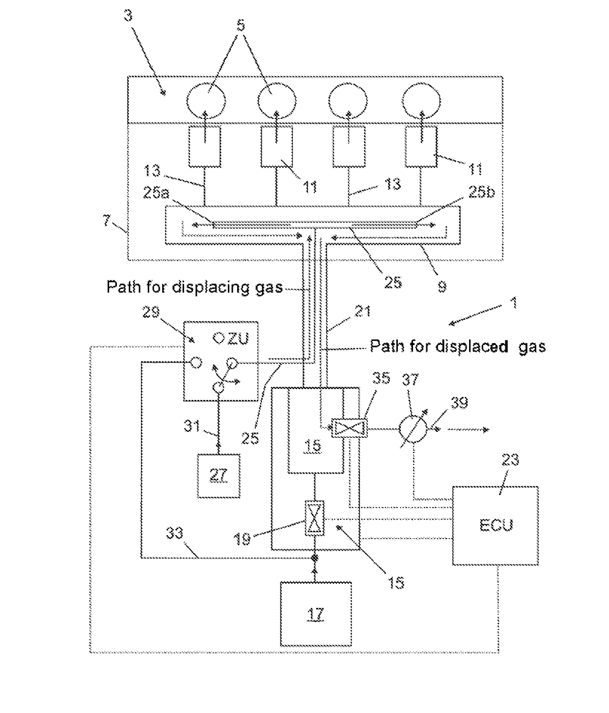
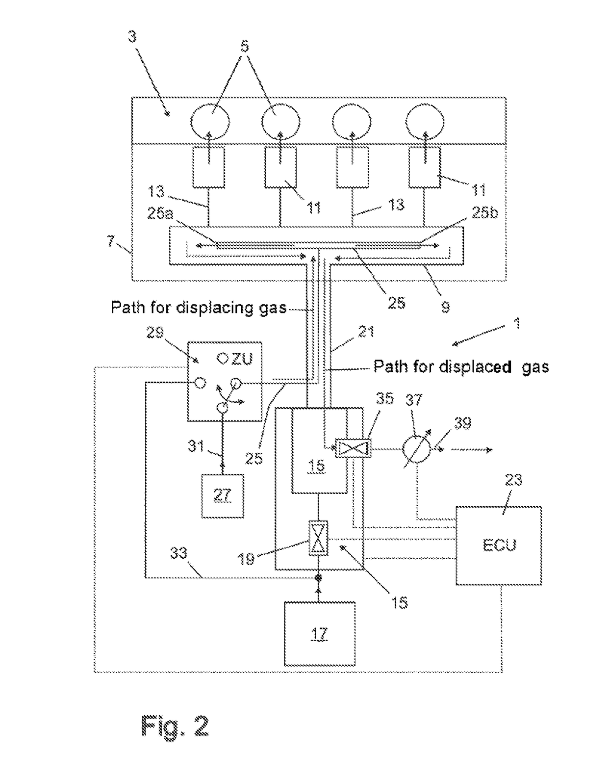
[0036]FIG. 2 shows a gas engine arrangement 1 according to the invention by way of example, said arrangement having a gas engine 3, which is formed with a plurality of cylinders 5. As indicated in dashed lines, a fuel system part 7 of the gas engine 3 and a gas rail 9 thereof are encapsulated by a double wall here in order to meet the operating safety conditions applying to them.

[0037]A first gas or fuel gas (e.g. natural gas, biogas etc.) can be supplied to a gas metering device 11 for each cylinder 5 or to a plurality of gas metering devices 11 of the gas engine 3 via the gas rail 9 (gas manifold bar) of the gas engine 3. The gas metering devices 11 are provided as gas injection valves, in particular as solenoid valves for producing an ignitable mixture in a combustion chamber of each cylinder 5. Each of the gas metering devices 11 can receiv...


PUM


Abstract

Gas engine arrangement having a gas engine, a gas rail, via which a first gas in the form of fuel gas can be supplied to at least one gas metering device of the gas engine, and a gas control section, which is designed to supply fuel gas to the gas rail via a supply path on the outflow side. A purge line is passed into the gas rail. The gas engine arrangement is designed to selectively supply fuel gas or a second gas to the purge line, and the gas engine arrangement is designed to displace gas from the gas rail and to discharge it via the supply path when the fuel gas or second gas is supplied to the purge line.

Description

CROSS-REFERENCE TO RELATED APPLICATIONS[0001]The present application claims priority of DE 10 2014 004 013.5, filed Mar. 20, 2014, the priority of this application is hereby claimed and this application is incorporated herein by reference.BACKGROUND OF THE INVENTION[0002]The present invention relates to a gas engine arrangement having a gas engine and a gas rail.[0003]Gas engines, especially those which are used for mobile applications, e.g. in operating environments such as ships, commercial vehicles and the like, are subject to the requirement, as regards emergency stop situations, of adopting a safe operating state as they shut down. In general, this necessitates purging the gas rail and feeding it with inert gas.[0004]FIG. 1 shows solutions in accordance with the prior art, in which, as can be seen, a high outlay is incurred for such purging inasmuch as it is often necessary in this case to pierce the double wall 7a′ surrounding and protecting the fuel system 7′ of the gas engin...

Claims


Application Information

Patent Timeline
Patent Type & Authority Patents(United States)
IPC IPC(8): F02M21/02F02D41/00F02N19/00F02D19/02
CPCF02M21/0227F02D19/025F02D41/0027F02M21/0245F02M21/0293F02N19/00Y02T10/32Y02T10/30
Inventor PRUNNBAUER, JANMATTHIES, JORG
Owner MOTOREN UND TURBINEN UNION MUNCHEN GMBH
Why Eureka
Try Eureka