
Adjuster track assembly for a vehicle seat

a technology for vehicle seats and track assemblies, which is applied in the direction of movable seats, mechanical equipment, transportation and packaging, etc., can solve the problems of high number of rejected parts, warranty issues, and quality, and achieve the effect of reducing rotational efforts and high track efforts

Active Publication Date: 2017-08-22
BROSE FAHRZEUGTEILE GMBH & CO KG
View PDF14 Cites 1 Cited by
  • Summary
  • Abstract
  • Description
  • Claims
  • Application Information

AI Technical Summary

Benefits of technology

The present invention aims to reduce the effort required to rotate the rollers in an adjuster track assembly, which can result in lower track efforts. It also aims to minimize scrap and defective parts, as well as improve the quality and speed of operation. In simple terms, the objective is to make the assembly process more efficient and effective.

Problems solved by technology

This results in high track efforts, leading to a higher number of rejected parts and quality as well as warranty issues.

Method used


Image

  • Adjuster track assembly for a vehicle seat
  • Adjuster track assembly for a vehicle seat
  • Adjuster track assembly for a vehicle seat

Examples


Embodiment Construction

[0030]Subsequently, embodiments of the invention shall be described in detail with reference to the drawings. In the drawings, like reference numerals designate like structural elements.

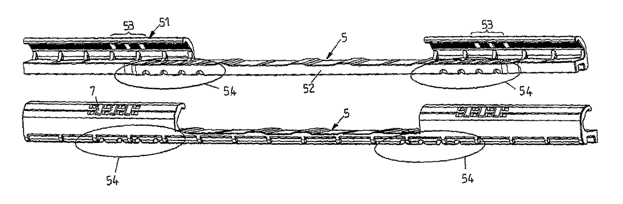
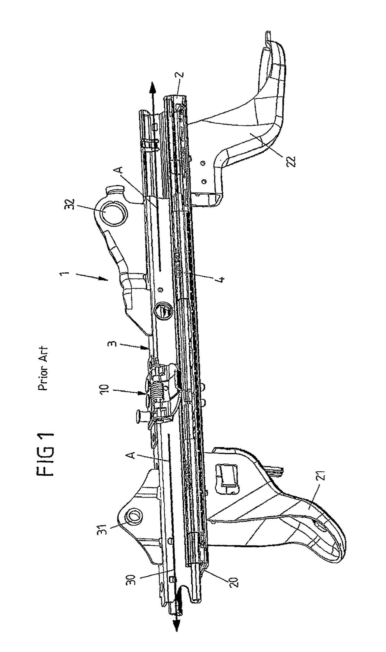
[0031]FIG. 6 shows in different perspective views a bearing element 5 which according to FIG. 1 is to be inserted into a stationary lower rail 2 for guiding an upper rail 3 of an adjuster track assembly 1 for a vehicle seat and is preferably made of either plastic material or aluminium or an aluminium alloy.

[0032]The bearing element 5 is adapted to the structure and design of the lower bearing region which—according to FIG. 1—is formed by the curved ends of the horizontal leg 20 of the lower rail 2 and the vertical leg 30 of the upper rail 3. The bearing element 5 comprises a vertical leg 51 adapted to the vertical leg 20 of the lower rail 2 and a horizontal leg 52 adapted to the vertical leg 30 of the upper rail 3. The curved end of the vertical leg 51 of the bearing element 5 includes upper bearing...


PUM


Abstract

An adjuster track assembly for a vehicle seat includes an upper rail configured to be fastened to the vehicle seat and displaceable in a longitudinal direction, a stationary lower rail, a linear guide provided in the longitudinal direction between the upper rail and the lower rail which includes a bearing element for longitudinal guidance and support of the upper rail. The bearing element includes bearing cages with rollers accommodated within roller pockets having retention areas for guiding said rollers both in the longitudinal direction and the direction perpendicular to the longitudinal direction, and absorption areas for receiving or eliminating wear debris or abrasions.

Description

TECHNICAL FIELD[0001]The present invention relates to an adjuster track assembly for a vehicle seat.BACKGROUND[0002]As shown in FIG. 1 a conventional adjuster track assembly 1 for a vehicle seat has at least one stationary lower rail 2 connected to the vehicle floor via corresponding brackets 21, 22 and a movable upper rail 3 for receiving a vehicle seat via rear and front rockers 31, 32. The upper rail 3 and the lower rail 2 are embodied essentially as U-profiles. They are arranged here with respect to one another so that an essentially rectangular cross-sectional profile results. The lower rail 2 and the upper rail 3, viewed in cross-section each have two legs curved at the ends such that the upper rail 3 is guided in the lower rail 2 so as to be displaceable along the lower rail 2 in a forward and backward direction indicated by arrows A. Positioning of the vehicle seat in the longitudinal direction of the vehicle body can thus be adjusted by sliding the upper rail 3 along the lo...

Claims


Application Information

Patent Timeline
Patent Type & Authority Patents(United States)
IPC IPC(8): B60N2/07
CPCB60N2/0722B60N2/07B60N2/0702B60N2/0705F16C29/04F16C29/08F16C33/3806F16C33/3856F16C33/3887F16C33/4605F16C33/4635F16C33/467
Inventor IOPPOLO, LEO
Owner BROSE FAHRZEUGTEILE GMBH & CO KG
Features
  • Generate Ideas
  • Intellectual Property
  • Life Sciences
  • Materials
  • Tech Scout
  • Unparalleled Data Quality
  • Higher Quality Content
  • 60% Fewer Hallucinations
Learn More