
Spectrometric systems and methods for improved focus localization of time- and space-varying measurements

a technology of time and space, applied in the direction of optical radiation measurement, diagnostics using spectroscopy, instruments, etc., can solve the problems of ineffective operation of pulse oximeter equipment, inability to accurately measure arterial haemoglobin saturation, and lack of quantitative monitoring tools in current medical practice of deteriorating cardiovascular status

Active Publication Date: 2017-08-22
MAYO FOUND FOR MEDICAL EDUCATION & RES
View PDF19 Cites 23 Cited by
  • Summary
  • Abstract
  • Description
  • Claims
  • Application Information

AI Technical Summary

Benefits of technology

The device enables precise and quantitative measurement of arterial haemoglobin saturation and other material components, providing valuable insights into cardiovascular health and improving monitoring capabilities beyond the limitations of existing pulse oximeters.

Problems solved by technology

While techniques exist that allow qualitative monitoring of the level of arterial blood and tissue oxygen saturation, the current medical practice appears to lack a tool for quantitative monitoring of deteriorating cardiovascular status from the initial cardiovascular event or acute trauma through arrival at a medical facility.
PULSE OXIMETER EQUIPMENT is not typically capable of functioning effectively during cardiopulmonary bypass or at extreme low-flow states, and is not at present intended as a means for the measurement of blood flow or blood volume.
“Given these limitations, PULSE OXIMETER EQUIPMENT does not provide precise measurements of arterial haemoglobin saturation.

Method used


Image

  • Spectrometric systems and methods for improved focus localization of time- and space-varying measurements
  • Spectrometric systems and methods for improved focus localization of time- and space-varying measurements
  • Spectrometric systems and methods for improved focus localization of time- and space-varying measurements

Examples


Embodiment Construction

[0078]References throughout this specification to “one embodiment,”“an embodiment,”“a related embodiment,” or similar language mean that a particular feature, structure, or characteristic described in connection with the referred to “embodiment” is included in at least one embodiment of the present invention. No portion of this disclosure, taken on its own and / or in connection with a figure, is intended to provide a complete description of all features of the invention.

[0079]In the drawings, like numbers represent the same or similar elements wherever possible. No single drawing is intended to support a complete description of all features of the invention. In other words, a given drawing is generally descriptive of only some, and generally not all, features of the invention and may, for the purposes of simplification of the drawing, contain not all elements of a particular view or all features that can be presented. The invention may possibly be practiced without one or more of the...


PUM

PropertyMeasurementUnit
angle of divergenceaaaaaaaaaa
FWHMaaaaaaaaaa

Abstract

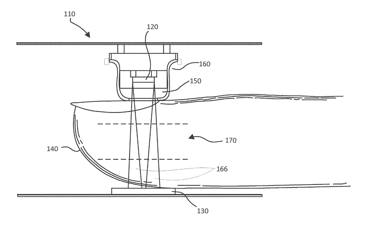
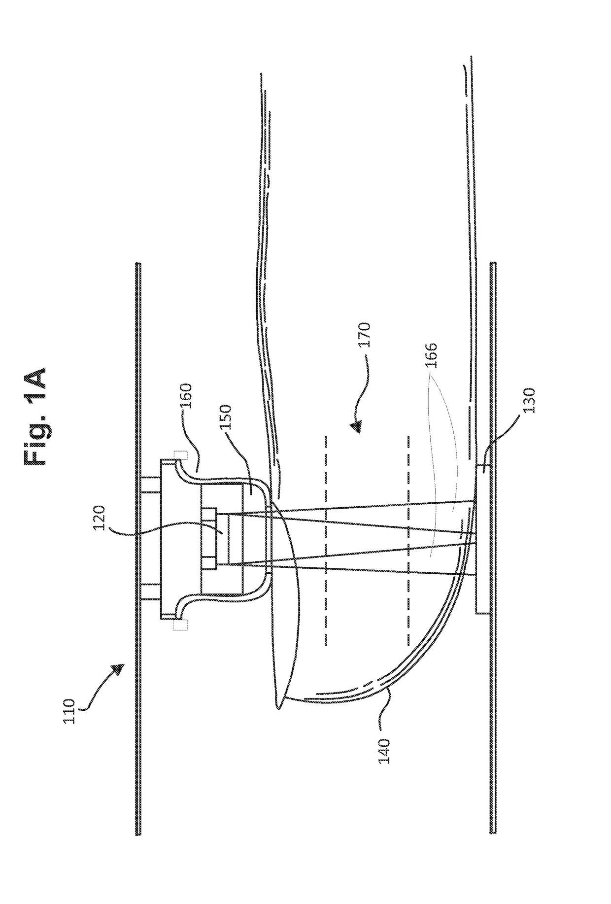
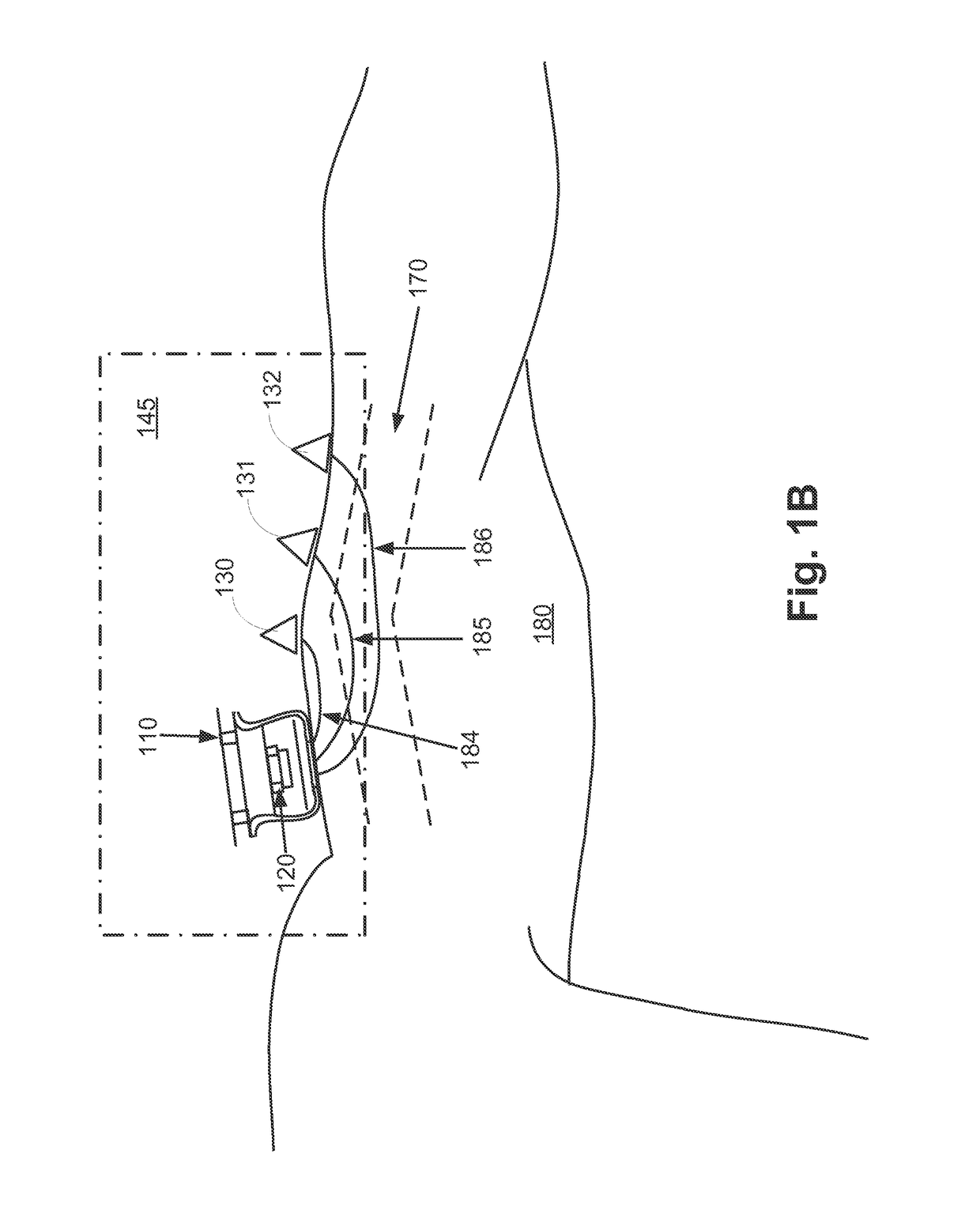
A system and method of dynamically localizing a measurement of parameter characterizing tissue sample with waves produced by spectrometric system at multiple wavelengths and detected at a fixed location of the detector of the system. The parameter is calculated based on impulse response of the sample, reference data representing characteristics of material components of the sample, and path lengths through the sample corresponding to different wavelengths. Dynamic localization is effectuated by considering different portions of a curve representing the determined parameter, and provides for the formation of a spatial map of distribution of the parameter across the sample. Additional measurement of impulse response at multiple detectors facilitates determination of change of the measured parameter across the sample as a function of time.

Description

CROSS-REFERENCE TO RELATED APPLICATIONS[0001]This patent application is a national stage entry of International Application No. PCT / US2013 / 038623 filed on Apr. 29, 2013, which claims the benefit of and priority from U.S. provisional patent application Ser. Nos. 61 / 640,682, filed on Apr. 30, 2012; 61 / 789,565, filed on Mar. 15, 2013; 61 / 794,196, filed on Mar. 15, 2013; and 61 / 794,515, filed on Mar. 15, 2013. Disclosure of each of the abovementioned patent applications is incorporated herein by reference in its entirety.TECHNICAL FIELD[0002]The present invention relates to spectroscopic systems and methods of transmitting and receiving two or more concurrent signals and systems and methods enabling improved measurement focus localization of time- and space-varying spectrometer measurements, with additional uses for volume and volume variation measurements and challenge based property measurements.BACKGROUND OF THE INVENTION[0003]The assessment of arterial blood and tissue oxygen satura...

Claims


Application Information

Patent Timeline
Patent Type & Authority Patents(United States)
IPC IPC(8): G01J3/00A61B5/1455G01N21/49A61B5/145G01J3/42A61B5/00G01N33/49G01J3/02
CPCG01J3/42A61B5/0075A61B5/14532A61B5/14552G01J3/0237G01N21/49G01N33/4925
Inventor HAIDER, CLIFTON R.GILBERT, BARRY K.DELP, GARY S.ROSE, JAMES A.
Owner MAYO FOUND FOR MEDICAL EDUCATION & RES
Learn More