3-D polarimetric imaging using a microfacet scattering model to compensate for structured scene reflections

a scattering model and structured scene technology, applied in the field of 3d polarimetric imaging, can solve the problems of limited calibration map accuracy and corrupt 3-d image, and achieve the effect of accurately generating the surface normal calibration map

Active Publication Date: 2017-08-22
RAYTHEON CO
View PDF18 Cites 13 Cited by
  • Summary
  • Abstract
  • Description
  • Claims
  • Application Information

AI Technical Summary

Benefits of technology

[0012]The present invention provides a system and method for more accurately generating the surface normal calibration maps φ(AoLP) and θ(DoLP,φ) to compensate for structured scene reflections. The method does not assume a single idealized reflective source or a single dominant emissive source. The method does not assume that each object pixel is a combination of specular and diffuse components and does not require a large number of external sources at different locations to adequately populate the calibration maps.

Problems solved by technology

If uncompensated, the structured scene reflections can introduce a bias in the calibration maps that corrupts the 3-D image.
Furthermore, the accuracy of the calibration maps is limited by the assumption that each object pixel is a combination of a specular component and a diffuse component.

Method used


Image

  • 3-D polarimetric imaging using a microfacet scattering model to compensate for structured scene reflections
  • 3-D polarimetric imaging using a microfacet scattering model to compensate for structured scene reflections
  • 3-D polarimetric imaging using a microfacet scattering model to compensate for structured scene reflections

Examples


Embodiment Construction

[0030]Known techniques for 3-D polarimetric imaging are neither sufficiently robust nor accurate to have achieved commercial viability. These techniques are either predicated upon an assumption of lighting conditions that is not realistic (e.g., no structured scene reflections) or upon an assumption of the measured reflectance due to structured scene reflections (e.g., a combination of specular and diffuse reflection) that is often inaccurate and produces sparsely populated calibration maps.

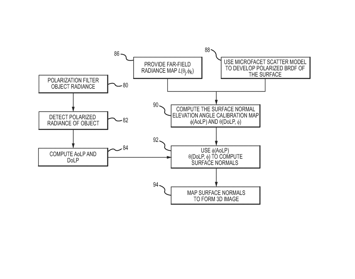
[0031]The present technique for 3-D polarimetric imaging, and more particularly for generating the surface normal calibration maps φ(AoLP) and θ(DoLP,φ), makes neither assumption. This approach uses Stokes vectors to describe the polarization state of the structured scene reflections and Mueller calculus to describe the effect of the object surface on the polarization state of the light. A microfacet scattering model is used to develop the functional form of a polarized bidirectional reflectance ...


PUM


Abstract

A system and method for more accurately generating the surface normal calibration maps φ(AoLP) and θ(DoLP,φ) to compensate for structured scene reflections for 3-D polarimetric imaging. This is accomplished using a microfacet scattering model to develop the functional form of a polarized bidirectional reflectance distribution function (BRDF) of the object surface. The ambient radiance is ray traced to the BRDF to create the calibration maps φ(AoLP) and θ(DoLP,φ), which may be combined into a single calibration map θ(DoLP, AoLP). These maps are applied to the AoLP and DoLP images to compute an array of surface normals, which are then mapped to form a 3-D image of the object.

Description

BACKGROUND OF THE INVENTION[0001]Field of the Invention[0002]This invention relates to 3-D polarimetric imaging, and more particular to a method of generating the surface normal calibration maps φ(AoLP) and θ(DoLP,φ) to compensate for structured scene reflections.[0003]Description of the Related Art[0004]Imaging detectors, such as focal plane arrays (FPAs), generally include an array of pixels, each pixel including a photo-detector that generates a signal responsive to light generated or reflected by an object. These signals are collected and combined such that a 2-D digital image of the object can be created. Pixelated filter arrays positioned in a fixed location over the detector array are widely used in commercial imaging systems to provide hyperspectral capability. For example, digital cameras use fixed-in-place pixelated filter arrays for color (RGB) photography. These filters reduce the amount of light that reaches the imaging pixel (for example, a red filter reflects blue and...

Claims


Application Information

Patent Timeline
Patent Type & Authority Patents(United States)
IPC IPC(8): G06T17/00G06T7/60G06T15/20G06T15/50G06T7/00
CPCG06T17/00G06T7/60G06T15/20G06T15/50G06T2200/04G01J4/04G01B11/24G06T7/70
Inventor FEST, ERIC C.
Owner RAYTHEON CO
Why Eureka
Try Eureka