
Mechanical superconducting switch

a superconducting switch and switch technology, applied in the direction of superconducting magnets/coils, magnetic bodies, domestic cooling apparatuses, etc., can solve the problems of limiting the achievable ramp rate and dissipation rate, affecting the cooling effect of the cryostat, and affecting the cooling effect of the switch. achieve the effect of conserving the atmospher

Active Publication Date: 2017-08-22
SIEMENS HEALTHCARE LTD
View PDF47 Cites 0 Cited by
  • Summary
  • Abstract
  • Description
  • Claims
  • Application Information

AI Technical Summary

Benefits of technology

The patent describes a new type of switch that uses superconducting wires to control the magnets in a cryogenic refrigerator. These wires are more stable than traditional ones, so the switch doesn't require a heater to open and close. The switch uses a mechanical action instead, which means it doesn't need a thermal heater and can have a very low resistance when open. This increases the speed at which the magnet can be cooled and de-cooled. The switch uses a vacuum or inert atmosphere to preserve its surface and a chemical getter to keep it clean. Overall, this new switch design is more stable and efficient than previous options.

Problems solved by technology

This renders the switch susceptible to temperature and wire instabilities.
Conventional superconducting switches have a limited open-circuit resistance and thus limit the achievable ramp rate and dissipate heat during energization and de-energization of the magnet.
This heater contributes to heat load on the cryostat and heat dissipation.
This dissipates power during ramp up and during ramp down.

Method used


Image

  • Mechanical superconducting switch
  • Mechanical superconducting switch
  • Mechanical superconducting switch

Examples


Embodiment Construction

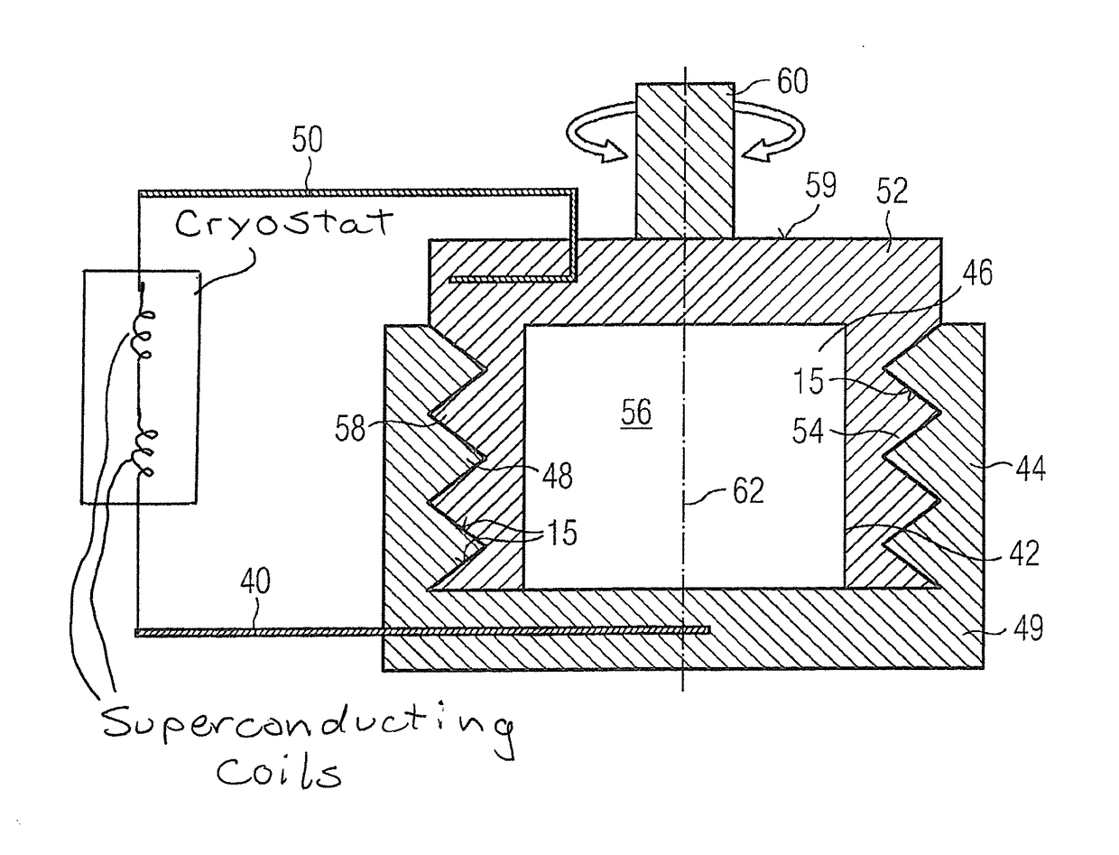
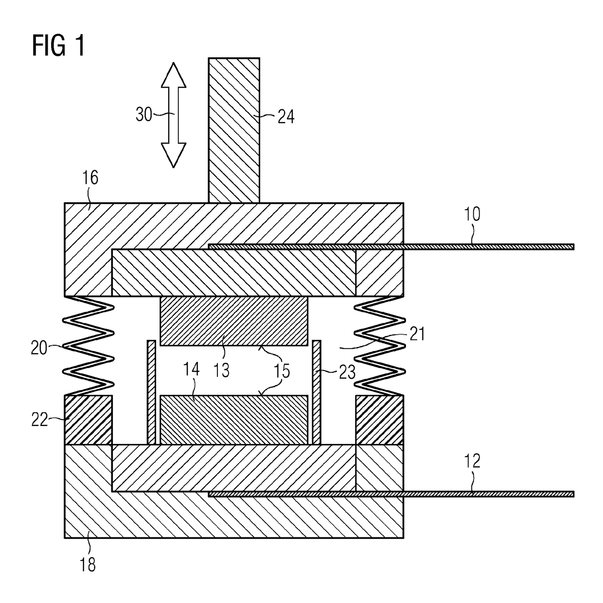
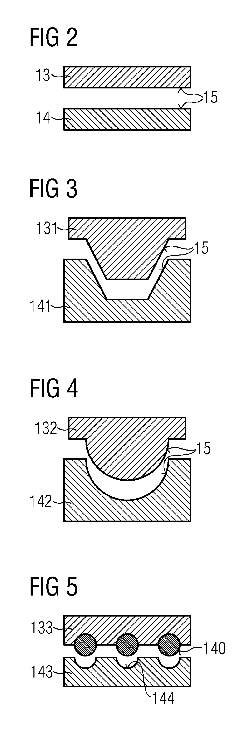
[0039]FIG. 1 shows a first example, in which superconducting wires 10, 12 are each embedded within upper 13 and lower 14 blocks of superconducting material, providing contact surfaces 15. Preferably, the material of at least one of the blocks is a ductile superconducting material, such as BiPb, NbTi, Nb. Upper 16 and lower 18 enclosure pieces retain the blocks and a bellows 20 provides a sealed enclosure 21 of variable height. An electrical insulator 22 may be provided if necessary, forming part of the enclosure, to prevent electrical conduction between the wires 10, 12 through the material of the enclosure. Mechanical actuation 30 may drive the contact surfaces 15 into electrical contact and separate them again. Although a mechanical actuator 24 is schematically illustrated, any appropriate means may be used to drive the two enclosure pieces 16, 18 toward one another and apart again to provide closing and opening of the switch. For example, a gas at a certain pressure may be sealed...


PUM

PropertyMeasurementUnit
resistanceaaaaaaaaaa
contact resistanceaaaaaaaaaa

Abstract

A mechanically operating superconducting switch has two superconducting wires, a respective end of each superconducting wire being embedded in a respective block of superconducting material. A mechanical arrangement is provided for driving respective contact surfaces of the blocks into physical contact with each other, and for separating those services.

Description

BACKGROUND OF THE INVENTION[0001]Field of the Invention[0002]The present invention concerns a mechanical superconducting switch, in particular for a superconducting magnetic resonance imaging (MRI) magnet.[0003]Description of the Prior Art[0004]Superconducting MRI magnets are formed of several coils of superconducting wire electrically connected in series and conventionally housed within a cryostat with a cryogenic refrigerator which cools the magnet to below a superconducting transition temperature of the material of the coils.[0005]Many conventional designs include a bath of liquid cryogen, for example liquid helium, which is maintained below its boiling point by a cryogenic refrigerator.[0006]However, more recent designs have sought to reduce or eliminate consumption of cryogens such as helium, for example by using cooling loops or “dry” also referred to as cryogen free magnets in which no liquid cryogen is used.[0007]It is necessary to provide a switch across the terminals of th...

Claims


Application Information

Patent Timeline
Patent Type & Authority Patents(United States)
IPC IPC(8): H01F6/00H01F6/04H01F6/06H01H33/00H10N60/20
CPCH01F6/06H01F6/008H01F6/04H01H33/004F25D19/006G01R33/3815H01H1/02H01H1/58
Inventor LAKRIMI, M'HAMEDTHOMAS, ADRIAN MARK
Owner SIEMENS HEALTHCARE LTD
Learn More