Battery pack temperature control structure for electric vehicles

a technology for electric vehicles and battery packs, applied in battery/fuel cell control arrangements, cell components, battery packs, etc., can solve the problem of increasing the maximum height of the battery pack case, and achieve the effect of achieving efficient temperature uniformity, short time, and good respons

Active Publication Date: 2017-08-22
NISSAN MOTOR CO LTD
View PDF18 Cites 5 Cited by
  • Summary
  • Abstract
  • Description
  • Claims
  • Application Information

AI Technical Summary

Benefits of technology

[0007]The present invention, which has been made in view of the above problems, has an object to provide a temperature control structure which is capable of suppressing the maximum height of a battery pack case a battery pack while achieving temperature uniformity of the battery module accommodated or mounted in the battery pack case for an electric vehicle.
[0009]Thus, the temperature control air from the air blowing port of the temperature control unit passes through the air duct and is discharged from the air blowing opening of the air duct to the module front upper region of the first battery module in the direction of the rear of the module. Here, the module front upper region protrudes in the vehicle upper direction above the top surface of the second battery module. Thus, when cooling air is blown first to the first battery module, the temperature of the first battery module lowers with good response, and then the ambient temperature of the internal space of the battery pack case is reduced to thereby cool the second battery module. Therefore, the temperature difference between the second battery module and the first battery module is reduced in a short time so that the temperature uniformity throughout the battery modules can be achieved efficiently. Further, it is noted that a step is formed in the battery module of two types which are disposed adjacent to each other in the inner space of the battery pack case. Thus, the air blowout opening is disposed opposite the module front upper region of the first battery module. Therefore, it is not necessary for the height of the air duct to be set higher than the height of the first battery module so that the maximum height of the battery pack case can be dimensioned without giving consideration to the height of the air duct. As a result, it is possible to hold the maximum height of the battery pack case reduced while achieving temperature uniformity of the battery modules housed in the battery pack case.

Problems solved by technology

Therefore, there is a problem that the maximum height of the battery pack case is increased by the amount corresponding to the height increased by the air duct.

Method used


Image

  • Battery pack temperature control structure for electric vehicles
  • Battery pack temperature control structure for electric vehicles
  • Battery pack temperature control structure for electric vehicles

Examples


first embodiment

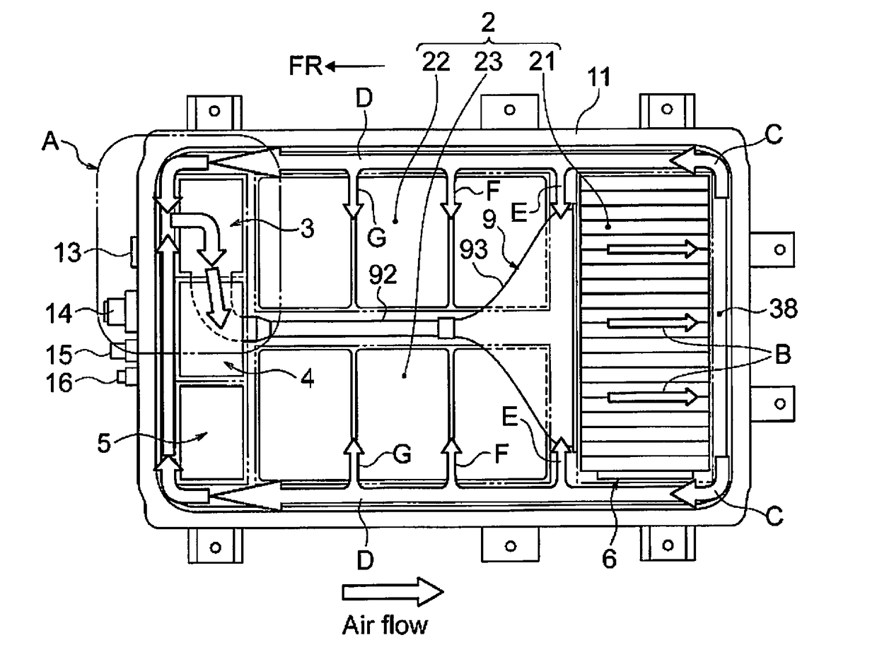
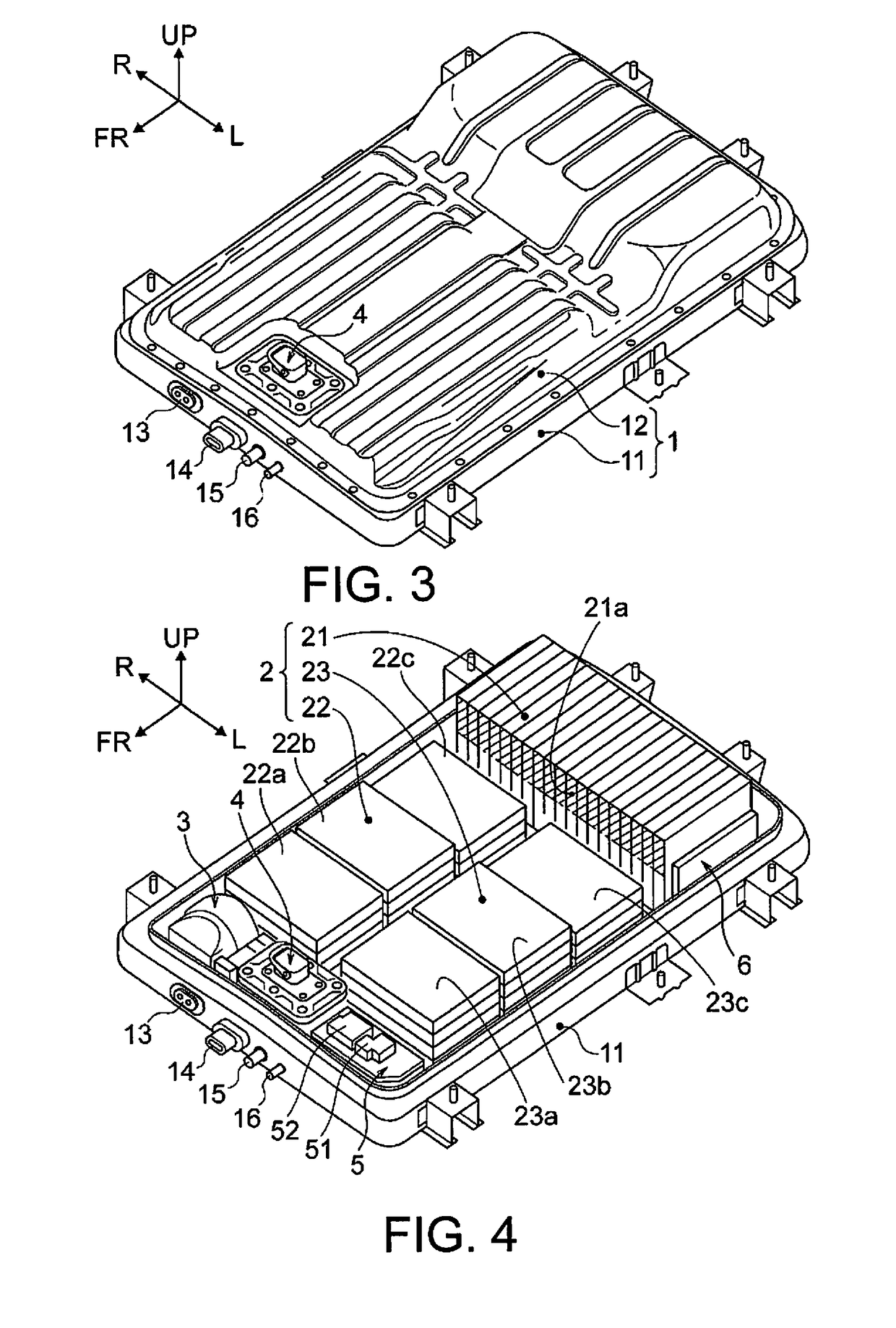
[0024]First, a description will be given of the configuration. The configurations of the battery pack temperature control structure for an electric vehicles in the first embodiment will be separately described in “VEHICLE MOUNTING STRUCTURE OF BATTERY PACK BP”, “PACKING COMPONENTS OF BATTERY PACK BP”, “REGION-PARTITIONING CONFIGURATION FOR CASE INTERNAL SPACE OF BATTERY PACK BP”, “TEMPERATURE CONTROL STRUCTURE OF BATTERY PACK BP”, and “RELEVANT STRUCTURE OF TEMPERATURE CONTROL UNIT AND SD SWITCH”, respectively.

Vehicle Mounting Structure of Battery Pack BP

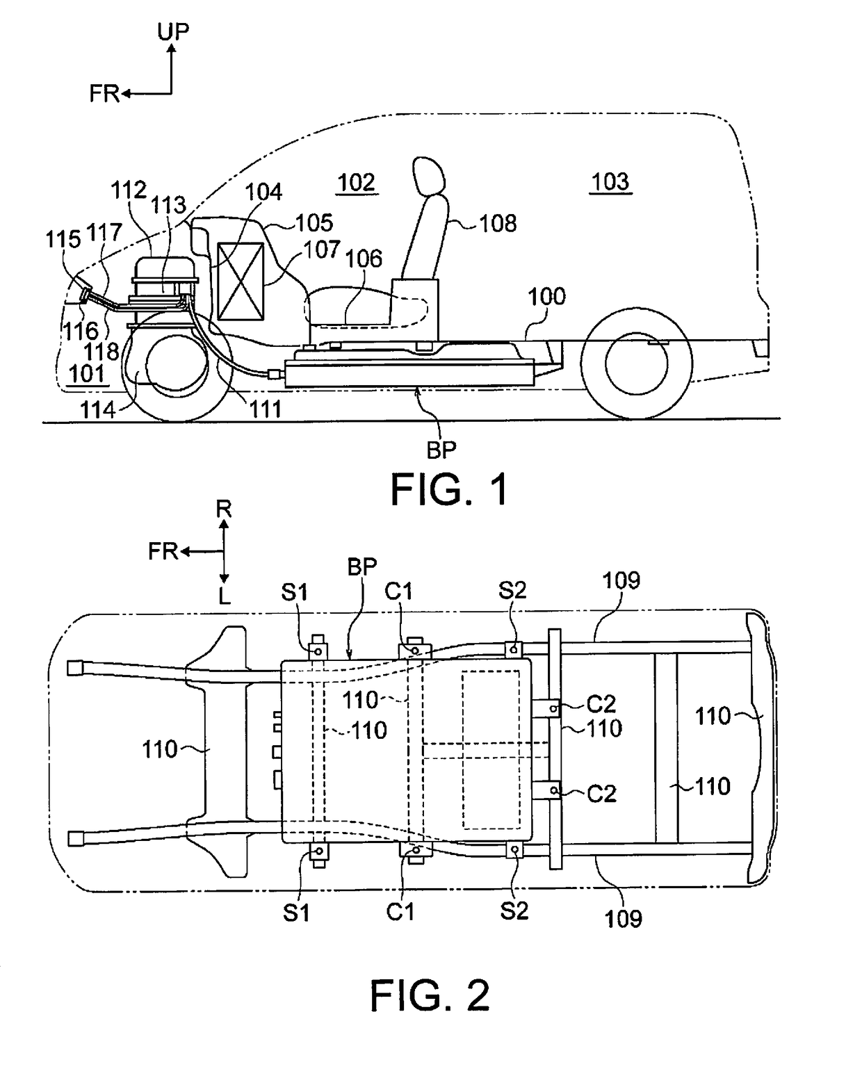
[0025]FIGS. 1 and 2 illustrate a schematic bottom view and a schematic side view respectively showing an electric vehicle of one box type with battery pack BP adopting the structure of the first embodiment. Below, with reference to FIGS. 1 and 2, a description is given of the structure of the vehicle battery pack BP.

[0026]As shown in FIG. 1, the battery pack BP is located underside of a vehicle-body floor 100 and arranged at a centr...


PUM

PropertyMeasurementUnit
temperatureaaaaaaaaaa
heightaaaaaaaaaa
sizeaaaaaaaaaa

Abstract

A battery pack temperature control structure is provided for an electric vehicle, and basically includes first and second battery modules, a temperature control unit and an air duct. The first and second battery modules are disposed inside a battery pack case. The second battery module has a lower height than the first battery module. The temperature control unit has an air blowing port for blowing a temperature control air to the first and second battery modules. The air duct is connected to the air blowing port of the temperature control unit, and has an air blowout opening arranged to blow out the temperature control air to a front of the first battery module at a location above the top of the second battery module. The air blowout opening-extends in a vehicle width direction and blows out the temperature control air toward the first battery module.

Description

CROSS-REFERENCE TO RELATED APPLICATIONS[0001]This application is a U.S. National stage application of International Application No. PCT / JP2013 / 052791, filed Feb. 7, 2013, which claims priority to Japanese Patent Application No. 2012-034127 filed in Japan on Feb. 20, 2012. The entire disclosure of Japanese Patent Application No. 2012-034127 is hereby incorporated herein by reference.BACKGROUND[0002]Field of the Invention[0003]The present invention relates to a battery pack temperature control structure for an electric vehicle to control the temperature of the battery modules housed in the battery pack case.[0004]Background Information[0005]Conventionally, a cooling structure of the battery pack is known in which a cooling unit is provided in the vehicle front of the battery module which is accommodated and disposed in a battery pack case, and an air or ventilation duct having one end communicated with the cooling unit extends along the upper surface of the battery module in the vehic...

Claims


Application Information

Patent Timeline
Patent Type & Authority Patents(United States)
IPC IPC(8): H01M10/625H01M10/6563H01M10/613H01M10/6566H01M10/647H01M2/10B60L11/18B60L50/64H01M50/209H01M50/249
CPCH01M10/625H01M10/647H01M10/6563H01M10/613B60L11/1874B60L11/1875B60L11/1879H01M2/1077B60L2240/545H01M2220/20Y02T10/7005H01M50/209B60L50/64H01M50/249B60L58/26B60L58/27Y02T10/70Y02E60/10
Inventor TANIGAKI, TATSUNORIHATTA, KENTAROTSUJIMURA, NORIHISA
Owner NISSAN MOTOR CO LTD
Why Eureka
Try Eureka