Wireless power receiving apparatus
a power receiving apparatus and wireless technology, applied in the direction of electrical equipment, circuit arrangements, etc., can solve the problems of small power use efficiency, change in resonance condition, disturbance of resonant state, etc., and achieve the effect of short time scal
- Summary
- Abstract
- Description
- Claims
- Application Information
AI Technical Summary
Benefits of technology
Problems solved by technology
Method used
Image
Examples
first embodiment
Wireless Power Transmitting Apparatus
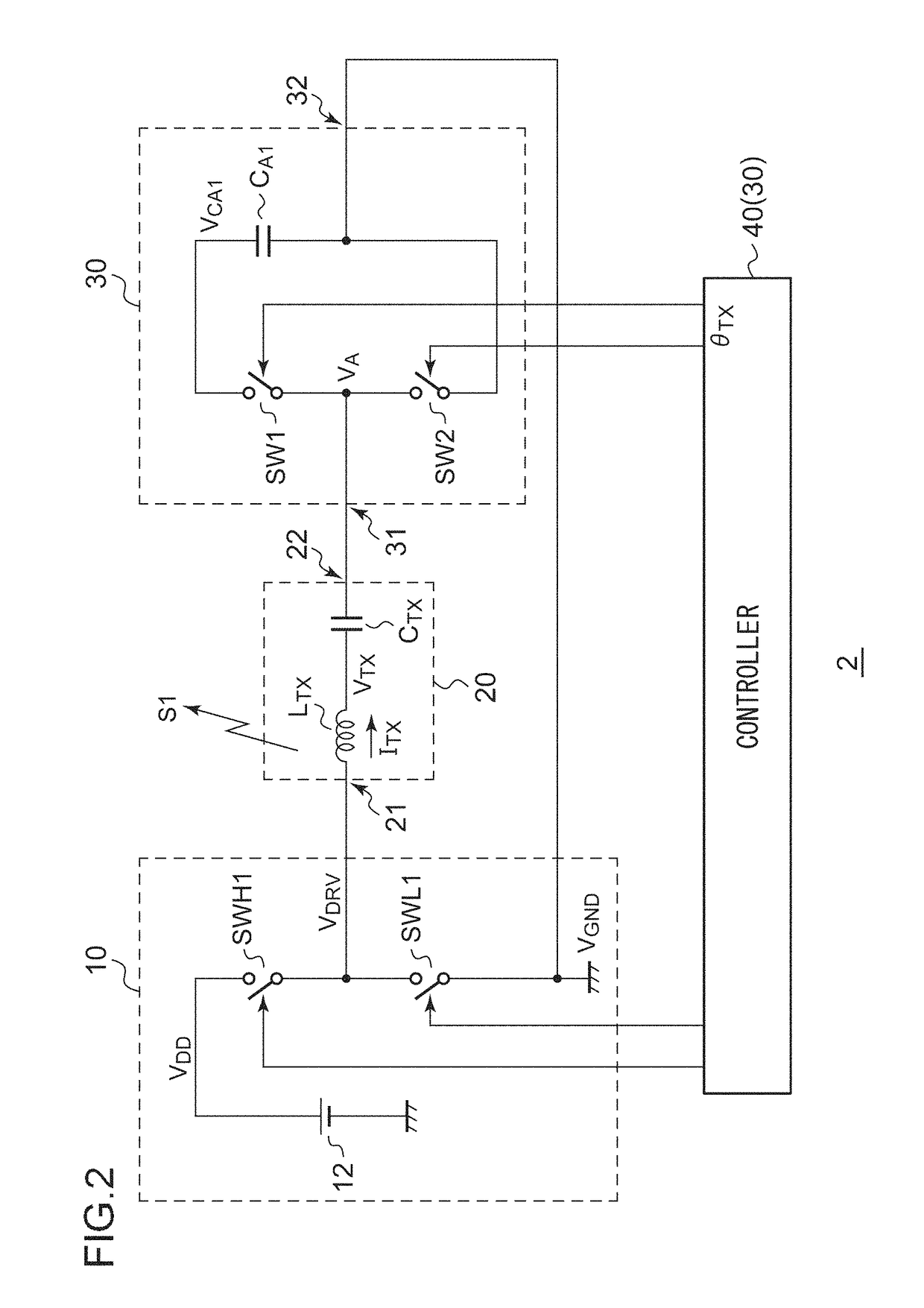
[0062]FIG. 2 is a circuit diagram showing a configuration of a wireless power transmitting apparatus 2 according to a first embodiment. The wireless power transmitting apparatus 2 transmits an electric power signal S1 to a wireless power receiving apparatus (not shown). As such an electric power signal S1, the wireless power transmitting apparatus 2 uses the near-field components (electric field, magnetic field, or electromagnetic field) of electromagnetic waves that have not yet become radio waves.
[0063]The wireless power transmitting apparatus 2 includes a power supply 10, a transmission antenna 20, an automatic tuning assist circuit 30, and a first controller 40.
[0064]The transmission antenna 20 includes a transmission coil LTX arranged between its first terminal 21 and its second terminal 22. A resonance capacitor CTX is arranged in series with the transmission coil LTX. The resonance capacitor CTX and the transmission coil LTX may also be mu...
second embodiment
[0163]Description has been made in the first embodiment regarding the automatic tuning assist circuit including the two switches SW1 and SW2. An automatic tuning assist circuit according to a second embodiment has a configuration including four switches. The automatic tuning assist circuit according to the second embodiment has the same block configuration as that of the first embodiment except for the automatic tuning assist circuit 80. Also, various kinds of modifications as described in the first embodiment may effectively be made for the second embodiment.
Wireless Power Receiving Apparatus
[0164]FIG. 22 is a circuit diagram showing a configuration of a wireless power transmitting apparatus 2 according to a second embodiment. The wireless power transmitting apparatus 2 transmits an electric power signal S1 to a wireless power receiving apparatus (not shown). The electric power signal S1 is configured using the near-field components (electric field, magnetic field, or electromagnet...
third embodiment
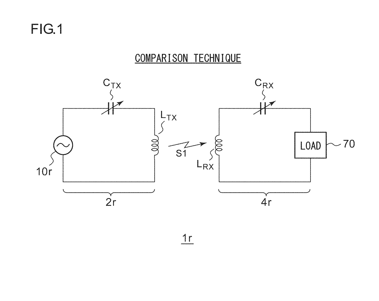
[0234]If a foreign substance such as a piece of metal is interposed between the transmission coil LTX and the reception coil LRX when the wireless power transmitting apparatus 2 or otherwise the wireless power receiving apparatus 4 described above in the first or second embodiment, or otherwise modifications thereof, is in the resonant state, this leads to a change in the condition for resonance, and the resonant state is disturbed. Also, if the degree of coupling between the transmission coil LTX and the reception coil LRX changes due to movement of the wireless power receiving apparatus 4r, this leads to a change in the condition for resonance, and the resonant state is disturbed. Alternatively, if there is power theft by a malicious user, the resonant state is also disturbed. Description will be made in the third embodiment regarding a technique for detecting a disturbance in the resonant state employed in the wireless power supply system 1r.
Wireless Power Transmitting Apparatus...
PUM
 Abstract
Description
Claims
Application Information
 - R&D
- Intellectual Property
- Life Sciences
- Materials
- Tech Scout
- Unparalleled Data Quality
- Higher Quality Content
- 60% Fewer Hallucinations
Browse by: Latest US Patents, China's latest patents, Technical Efficacy Thesaurus, Application Domain, Technology Topic, Popular Technical Reports.
© 2025 PatSnap. All rights reserved.Legal|Privacy policy|Modern Slavery Act Transparency Statement|Sitemap|About US| Contact US: help@patsnap.com


