Method and apparatus for electrolytically depositing a deposition metal on a workpiece

a technology of electrolytic depositing and workpiece, which is applied in the direction of electrolysis components, contacting devices, cell components, etc., can solve the problems of unsuitable current transfer and damage to electrical contact elements of current feeders, and achieve the effect of high curren

Active Publication Date: 2017-08-29
ATOTECH DEUT GMBH
View PDF15 Cites 0 Cited by
  • Summary
  • Abstract
  • Description
  • Claims
  • Application Information

AI Technical Summary

Benefits of technology

[0021]Consequently, one measure which is essential to the invention consists in the electrical contact elements being covered with the deposition metal in particular in the region of their contact areas, via which they are in contact with the workpieces during the metallization thereof, before being brought into contact with the workpiece. That means that preferably the same metal which also serves for the metal coating of the workpieces is used for covering the electrical contact elements. This makes possible, in particular, a particularly good current transfer between current feeding device and workpiece during the metallization of the workpieces. As a result of the measures according to the invention, the contact resistance becomes very low and the local evolution of heat correspondingly becomes very low.
[0022]It has been found that the problems explained above can be overcome by the measure according to the invention. A higher current can even be applied to the contact regions, and the workpiece can be coated with the deposition metal more rapidly.
[0023]In experiments it has furthermore been confirmed that an intimate mechanical contact—necessary for producing a favourable current transfer—between the electrical contact elements and the workpieces is advantageous, i.e. it is advantageous for the contact areas to bear areally as exactly as possible on the workpiece surface. For this purpose, the fixing of the contact element to the current feeding device can be fashioned in such a way that it is flexible within a specific region in order for example to compensate for a deviation of the contact area from the parallel position with respect to the transport plane. The elasticity of this fixing enables an automatic alignment of the contact area parallel to the workpiece surfaces, wherein the force with which the contact elements of the clamp are pressed together has to be high enough to align the contact areas with the workpiece surface. Preferably, the contact areas of the electrical contact elements are plane (planar) in order to achieve a good current transfer.
[0024]Furthermore, it can be advantageous if the base material, for example titanium, of the current feeding device, in particular of the contact element, has a certain roughness at the surface, in particular the contact area, in order to achieve an intimate and adhesively strong connection between the base material and the deposited metal of the contact coating. The roughness value Ra can be in a range of 0.2 to 10 μm, preferably 0.5 to 5 μm.
[0032]In accordance with a further preferred development of the method according to the invention, the workpiece is guided in a continuous apparatus for continuous electrolytic metal deposition on a preferably horizontal transport path. In the continuous installation, a plurality of current feeding devices are guided parallel to the transport path. In this case firstly the electrical contact elements of the current feeding devices are in electrical contact with the workpiece passing through the apparatus in accordance with method step (b) and, secondly, the workpiece is polarized via the electrical contact elements in accordance with method step (c). After method step (c), the electrical contact elements are firstly freed of the deposition metal deposited thereon. Subsequently, deposition metal is deposited on the electrical contact elements in accordance with method step (d). The electrical contact elements are then brought into contact with a further workpiece. Continuous methods of this type are extremely efficient since they are carried out in a compact installation, allow a high throughput and enable automatic operation.
[0036]In accordance with a further preferred development of the present invention, the at least one current feeding device is a contact clamp. With the contact clamps, the workpieces can be gripped in a clamping manner, for example, wherein a predefined pressure per unit area can be exerted on the workpiece surface by the electrical contact elements. A good current transfer from the electrical contact elements to the workpieces can thus be achieved.

Problems solved by technology

It has been found, however, that the measures proposed in EP 1 115 915 B1 suffice only to a limited extent to solve problems when making electrical contact with the workpieces in an electrolytic metallization installation.
Upon application of a very high current during the metallization, alongside the problems described in the cited document, it has additionally been observed that the electrical contact elements of the current feeders can also be damaged in the course of transferring the current to the workpieces.
This damage consists in the fact that the contact areas via which the contact elements of the current feeders are pressed onto the workpieces gradually erode and then become unsuitable for the current transfer.

Method used


Image

  • Method and apparatus for electrolytically depositing a deposition metal on a workpiece
  • Method and apparatus for electrolytically depositing a deposition metal on a workpiece
  • Method and apparatus for electrolytically depositing a deposition metal on a workpiece

Examples


Embodiment Construction

[0058]Identical reference signs in the figures designate elements having the same function.

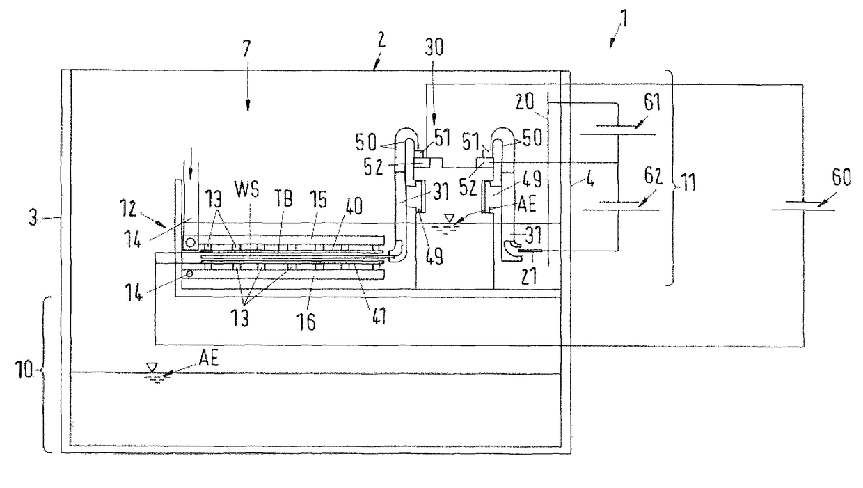
[0059]The continuous apparatus 1 illustrated in FIGS. 1, 2 and 3 serves for the continuous electrolytic deposition of metal on workpieces WS, here printed circuit boards. The apparatus 1 can serve for example for depositing copper. A copper deposition electrolyte is used in this case.

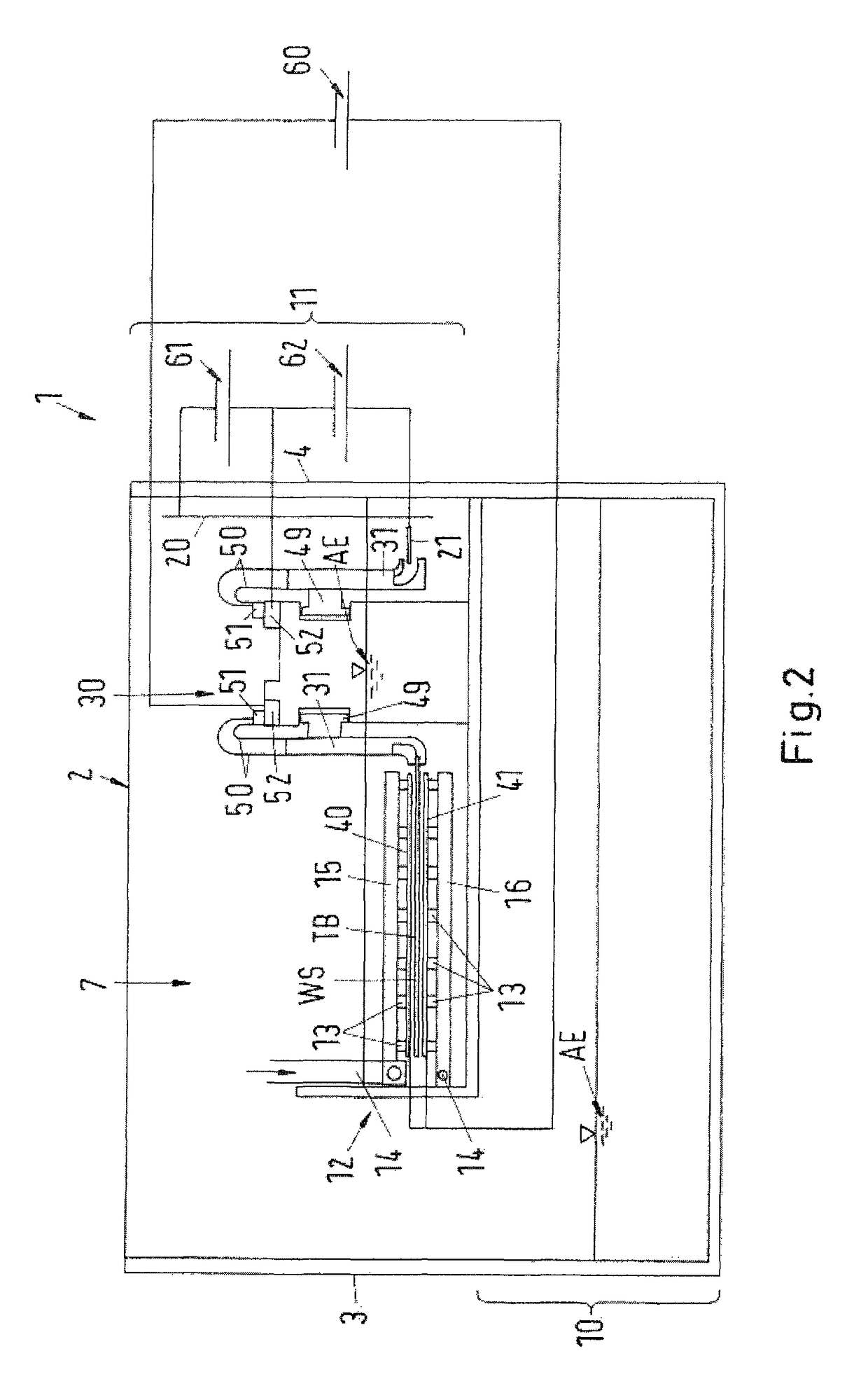
[0060]Installations 1 of this type have a housing 2 having a front wall 3, a rear wall 4, an entry wall 5 for the printed circuit boards WS, an exit wall 6 for the printed circuit boards, and a cover (not illustrated), which together define an interior 7.

[0061]The housing 2 is vertically divided into two: a reservoir for a deposition electrolyte AE is situated in a lower compartment 10 (“sump”). An upper compartment 11 is formed by a trough 12, in which the deposition electrolyte AE can likewise be held. Situated in this region is a transport path TB for the printed circuit boards WS that are conveyed through the ...


PUM

PropertyMeasurementUnit
thicknessaaaaaaaaaa
currentsaaaaaaaaaa
thicknessaaaaaaaaaa

Abstract

For improving the current transfer during the electrolytic metallization of workpieces, a method is proposed: (a) providing a metal depositing apparatus 17, in which the workpiece, at least one anode 40, 41 and a metal deposition electrolyte AE are arranged and which has a device for electric current generation 60 and at least one current feeding device 31 with in each case at least one electrical contact element 34, 35 for making electrical contact with the workpiece; (b)bringing the at least one electrical contact element 34, 35 into contact with the workpiece; and (c)feeding electric current to the workpiece via the at least one electrical contact element 34, 35 in order that the deposition metal deposits on the workpiece. Before method step (b), in a further method step (d), deposition metal is deposited on the at least one electrical contact element 34, 35.

Description

BACKGROUND OF THE INVENTION[0001]1. Field of the Invention[0002]The present invention relates to a method and an apparatus for electrolytically depositing an electrically conductive layer, in particular a metal, on a workpiece. The method and the apparatus are intended to be used in the production of planar, for example plate-shaped, workpieces or continuous foils, for example of printed circuit boards and conductor foils, wafers, solar panels, flat screen panels and the like, and during the metallization of workpieces with other forms that are used for example in the sanitary field, in the automotive industry, in mechanical engineering, or in other fields.[0003]2. Brief Description of the Related Art[0004]Installations for electrolytic metal coating are usually dipping bath installations or continuous installations. An apparatus of this type is described in DE 36 24 481 A1, for example. The arrangement has an electrolysis chamber, in which printed circuit boards are electrolyticall...

Claims


Application Information

Patent Timeline
Patent Type & Authority Patents(United States)
IPC IPC(8): C25D5/00C25D17/28C25D3/00C25D7/00C25D17/00C25D17/06C25D3/38H05K3/24
CPCC25D17/28C25D17/005C25D17/06H05K3/241H05K3/24C25D21/00C25D5/60Y10S204/07
Inventor BRITZ, DOMINIKSCHMITT, BERNDBOSE, BERNDMUCKLICH, FRANKSELZNER, CHRISTIAN
Owner ATOTECH DEUT GMBH
Why Eureka
Try Eureka